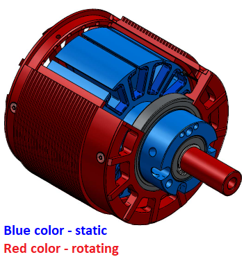
BLDC motors can additionally be classified as being of the "inrunner" or the "outrunner" type. The following drawing, courtesy of Revolt Motors, is of an outrunner BLDC.
Return to Top of Page Return to Main Menu
Bafang is a chinese company whose motors have a fairly solid reputation for qualit/price, and are commonly used for after-market ebike conversions.
Motor's Key Parameters:
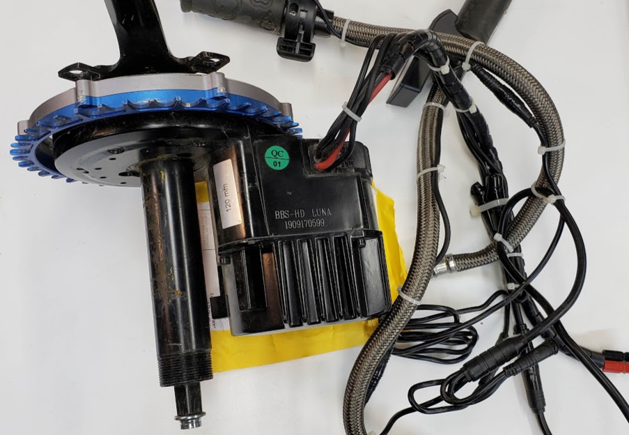
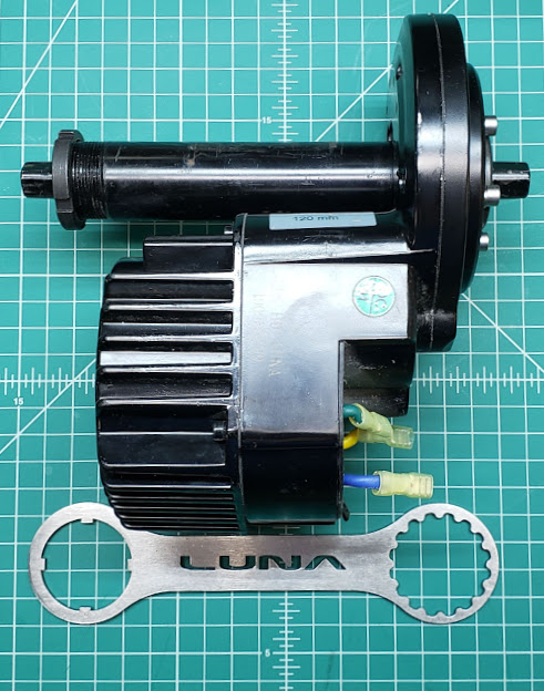
This shows the Luna-spec'ed version of the Bafang BBSHD mid-drive motor/controller combination. This version has the "Ludicrous" version of the Bafang controller built into the motor. The power ratings for this combination are higher than those for the 'stock' internal controller. This motor was originally used for the direct-drive (non fly-by-wire/FBW) eSkyBike on the indoor track at the farm. It was originally powered by the Luna "Mighty Mini" 14S2P battery pack.
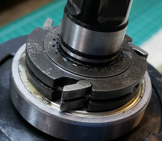
Showing the drive side of the BBSHD, with Luna's custom spyder mount and chainring. A stock Sugino 170mm crank arm is bolted to the end of the 4-tapered-flat axle end.
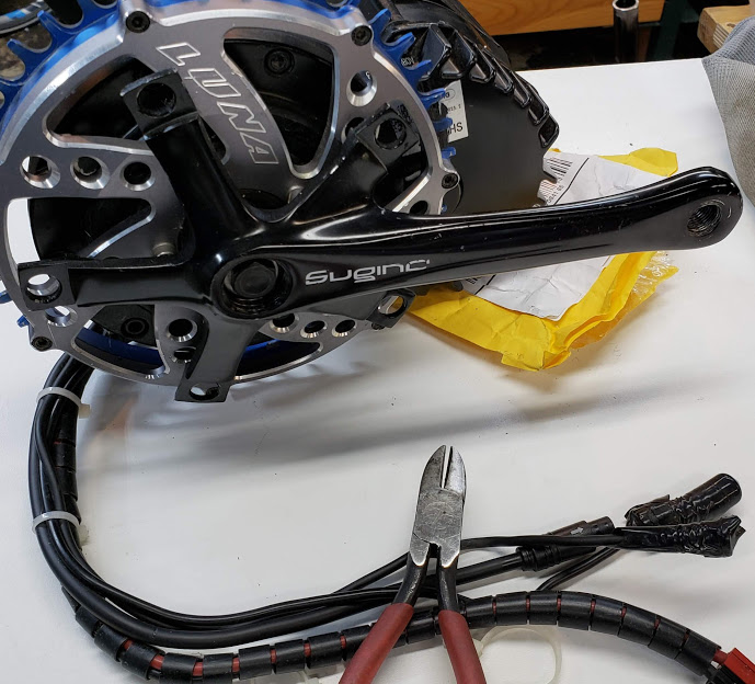
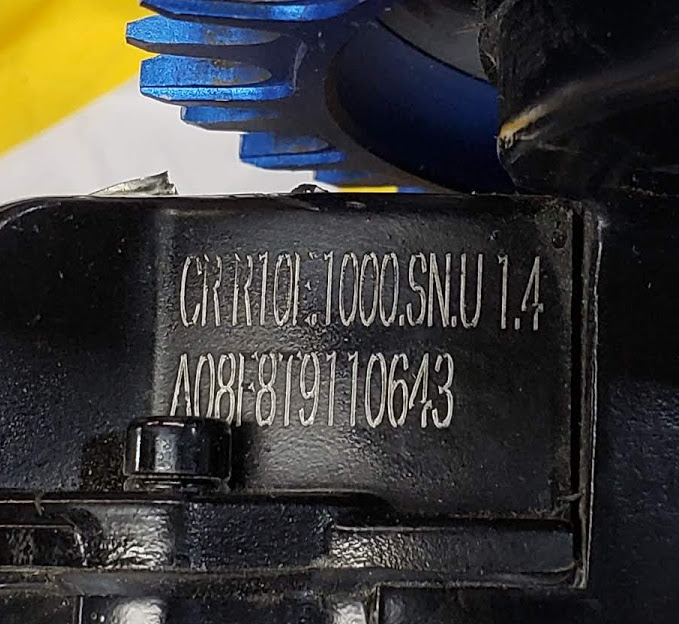
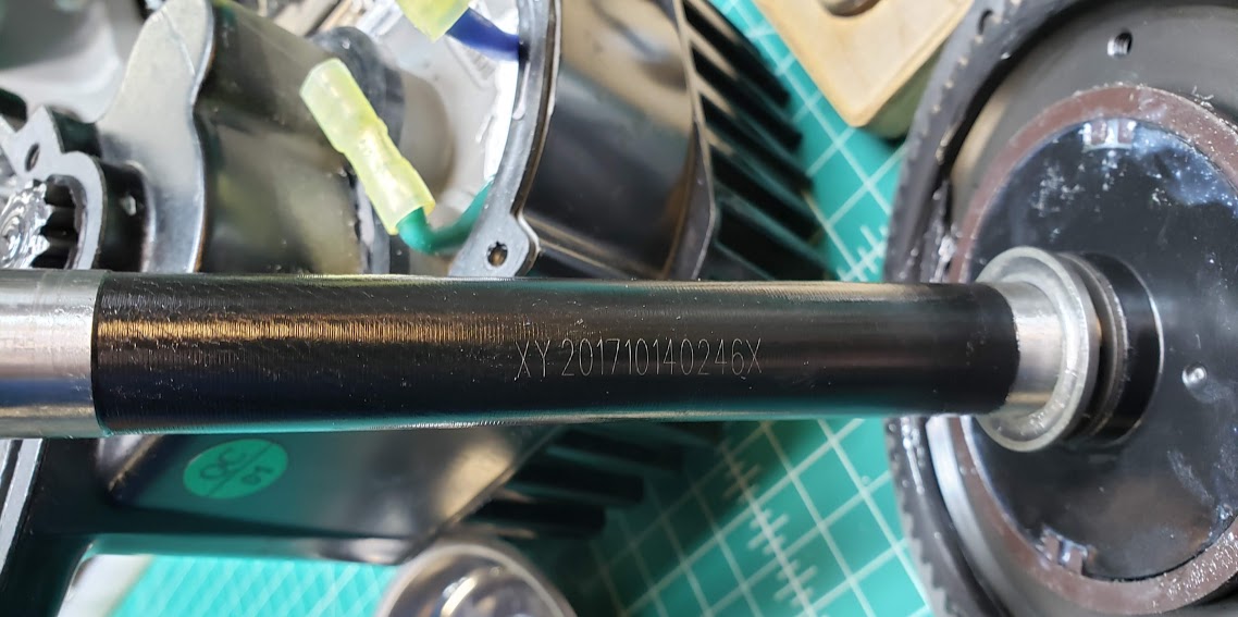
Photo of this motor's serial number and other indentifying information. The Luna-supplied assemblies are not identical to the Bafang factory models available through other vendors.
We are attempting to find out if this motor can be used 'in reverse' as a resistance unit. In this mode the motor becomes a generator/alternator, with its output imposed on the three phase wires. Unfortunately, it appears we have to remove the internal controller to have direct access to the motor's phase wires. What, if any, role the motor's stock inputs, display unit, freewheeling gears, or controller might have in its use a resistance unit is not known as of yet (14 Feb 2021). We currently assume that when forward pedaling this unit with no power connected and the controller removed, that the BLDC motor is spinning freely. The freewheel pawls are engaged with the large main gear, which is hard-connected to the small metal gear visible in the main gear housing. When this small metal gear turns, it turns (in either direction, meaning a 'hard' connection) the white nylon bevel gear, which is hard-connected to the steel pinion drive shaft of the motor. The real problem is that since the motor is in a sealed compartment, you can't prove the rotor is spinning for the same reason behind the refrigerator door open light challenge.
Testing the electrical output of the Luna BBSHD when cranked by hand: TBD, (14 Feb 2021)
See eSkyBike Resistance Unit for more information about this application.
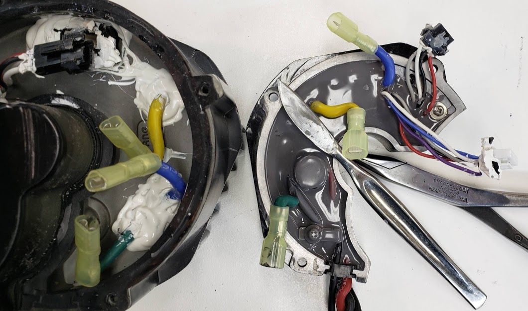
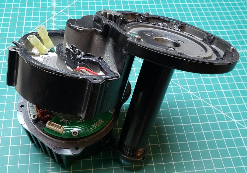
Removing the controller from the BBSHD involves removing three M4 cap screws (use 3mm allen wrench) and wiggling the potted controller off the rubber gasket. The controller is electrically connected to the actual motor via the three (big blue, yellow, green) phase wires, and two JST-SM connectors. One is a 6 wire bundle, while the other contains four wires. The six wires carry the motor's Hall sensor signals (plus heat sensor?), while the four wire (red, black, white, grey) bundle carries the signals from the crank/pedal cadence counter, also using Hall sensors.
Bottom view:
Side view:
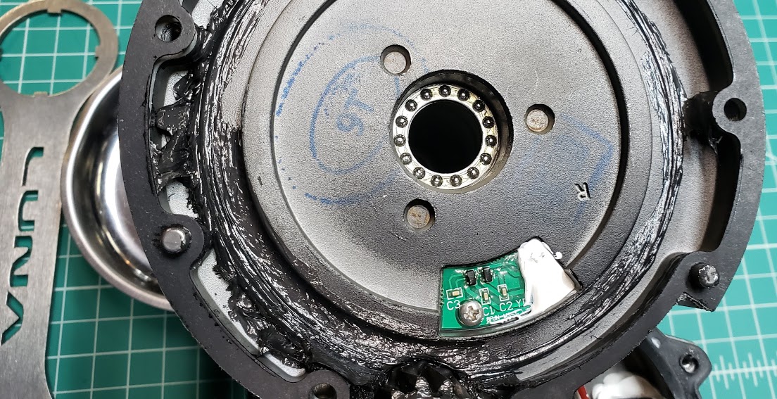
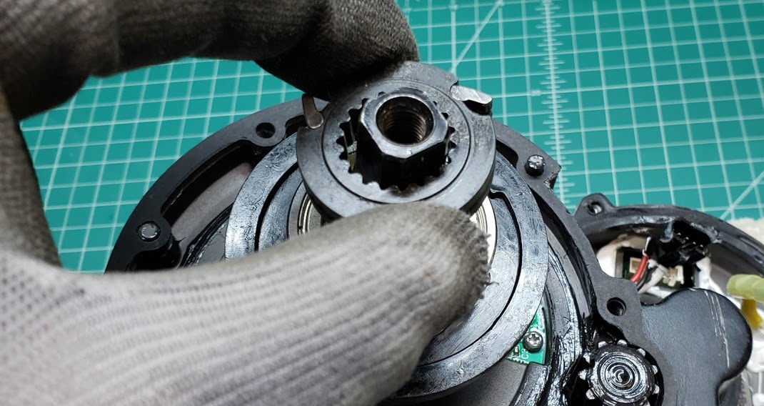
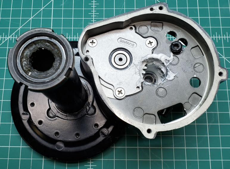
Drive side of motor with the large gear cover removed. The cover is sealed via a paper gasket and is easily removed using an M4 allen wrench to take out the 6 socket head screws. Note the small green PCB near the small spur gear. This board contains the Hall sensor assembly which sends pulses to the controller allowing it to calculate the RPM's of the crank/pedals.
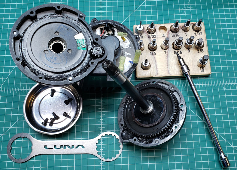
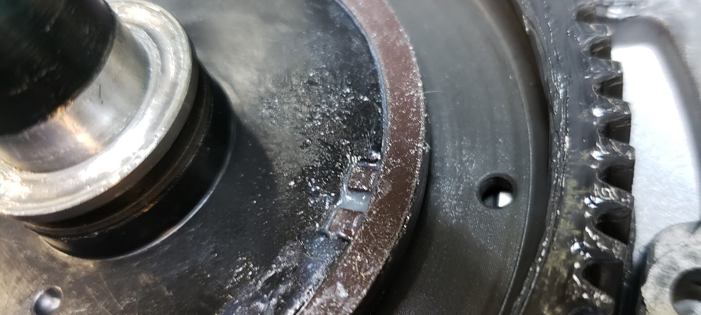
Showing the main drive shaft to which the cranks and pedals are attached. The brownish disc on the right/drive side of the shaft shows the two sets of magnets positioned 180 degrees apart which trigger the Hall sensor cadence counter green PCB module seen in the photo above.
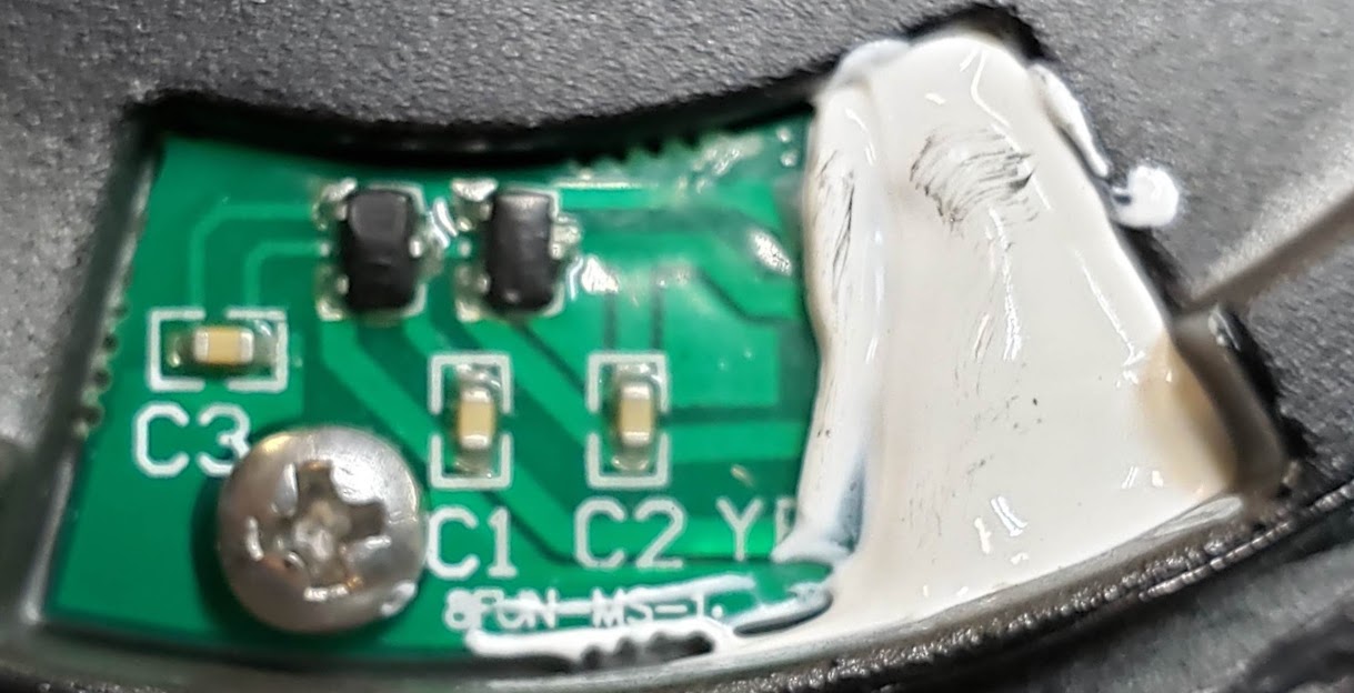
A closeup of the Hall sensor printed circuit board ("PCB"). It does not need to be removed when disassembling the motor side of the drive unit. The connection wires going to the controller are soldered onto the PCB and sealed under the white silicone material. The ball bearing race visible in the main drive shaft hole carries the axial loads of the shaft and simply drops into the hole. Make sure the race is clean and lubed on reassembly.
The two following photos show additional closeups of the Hall sensors and the magnet ring. You can clearly see the two black Hall sensor surface mount chips (with three leads), as well as the three capacitors (C1-C3) serving as support chips for the circuit. Note the "8Fun" label on the PCB, which suggests this part may be the same as used on Bafang's earlier models of this drive.
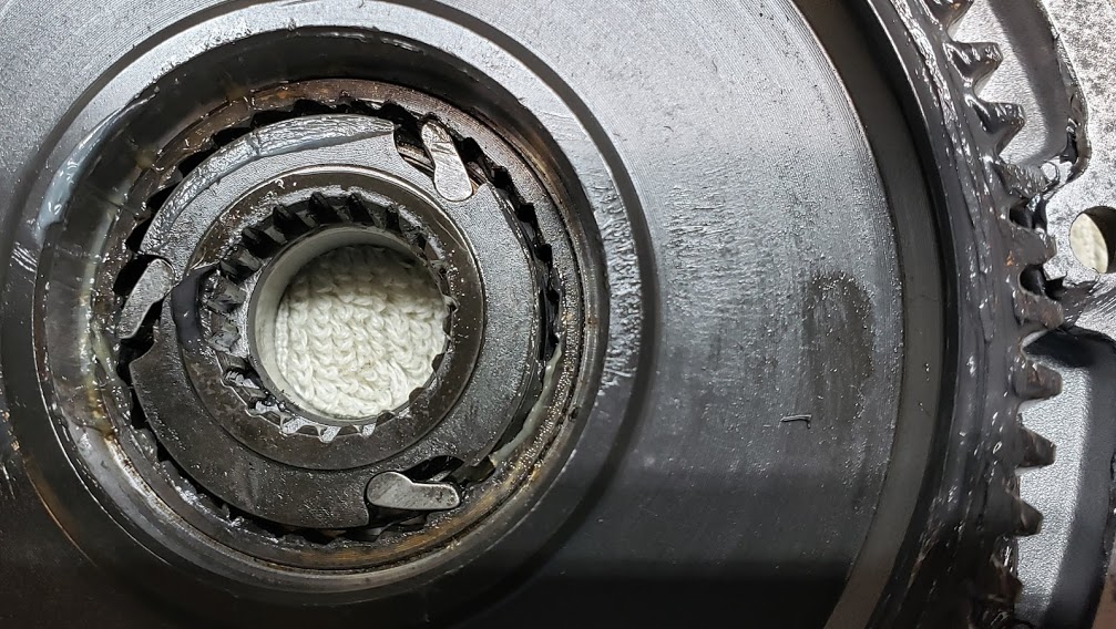
The unit's main drive shaft is coupled to the large gear on the drive side by this "freewheel" ratcheting pawl assembly. The rider's forward pedaling action, or the motor's forward assistance, results in the large gear being locked to the chainring (not attached in these photos) and causes the vehicle to go forward. When neither the rider nor the motor is pedaling forward, the pawls retract and de-couple the main gear/chainring from the motor. This allows the vehicle to "coast" without the motor being forced to turn. If pedaling forward doesn't cause the gear/chainring to turn, this freewheel unit likely has failed.
This assembly is easily removed from the drive shaft due to the matching splines on both parts. Unlike most bearings, it is not a "press fit", but a well-machined slide fit. On reassembly, make sure the direction of the pawls lines up correctly with the mating housing pressed into the big gear cover plate (next photo after this one).
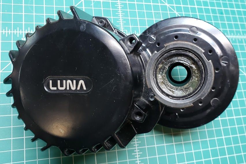
Here we see the left, non-drive side of the mid-drive unit, showing the Luna logo added to the Bafang BBSHD motor.
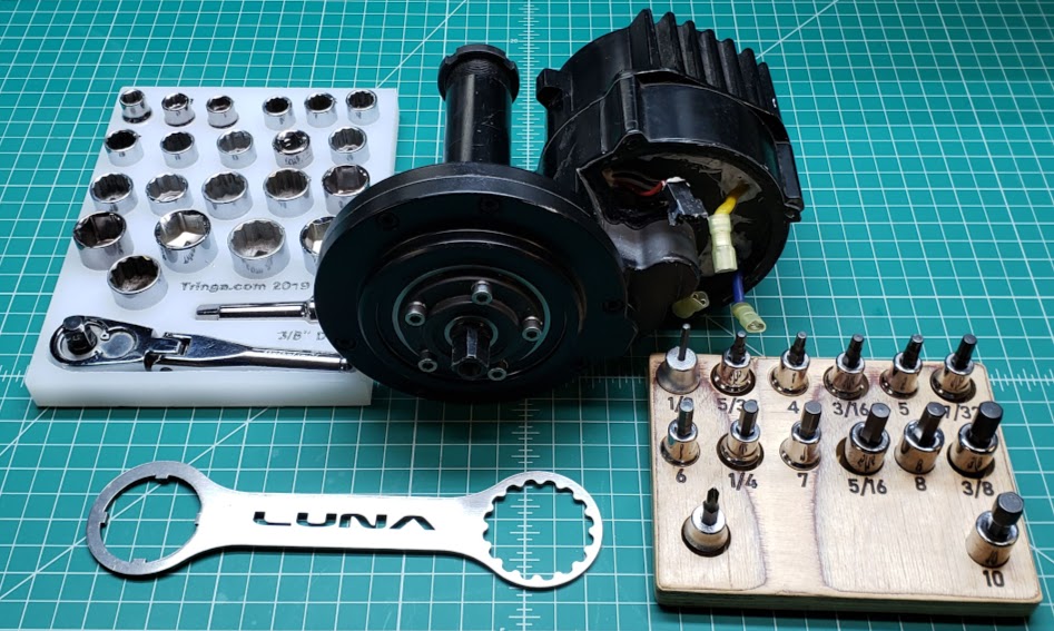
Removing the BLDC motor requires the use of a M3 allen head wrench to remove the 6 socket head screws holding the motor cover plate to the drive unit. Before doing this, the three (yellow, blue, green) phase wires must be freed from the while silicone glue and black rubber grommets used to seal the motor cavity from the controller compartment.
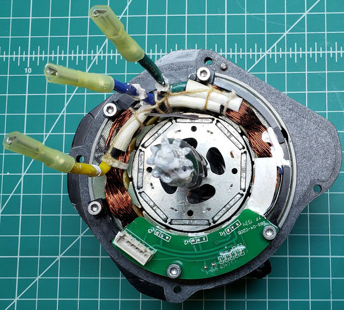
The white silicone sealer also needs to loosened/removed from the perimeter of the light-colored JST-PH-M6 connector, which is part of the PCB containing the motor's own 3 Hall sensors. The motor controller plugs into this connector to pick up the motor's Hall signals, which are separate from the two Hall sensors used to detect crank/pedal rotation. The connector and wires for the pedal cadence Hall sensors do NOT need to be undone. This pedal cadence assembly is identified as the 4 conductor black JST male plug, with red, black, white, and grey wires attached to it, with the wires going to the small PCB board mounted into the main gear housing.
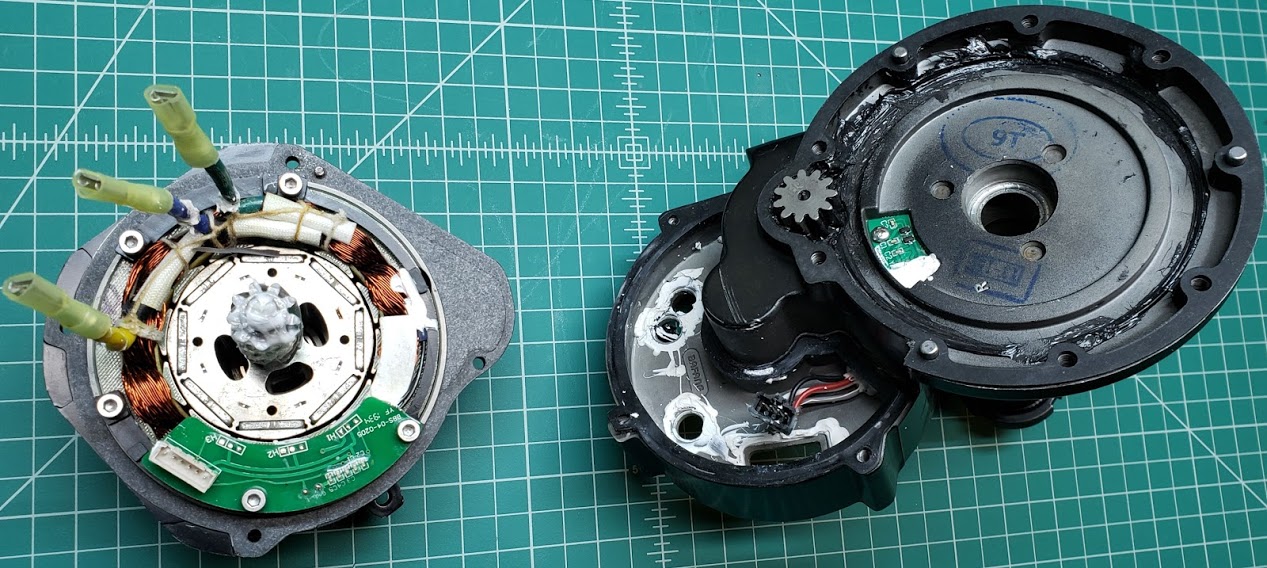
In this view of the motor removed from the drive unit, we can see the motor's steel bevel gear which drives a corresponding white plastic gear in the drive unit. It's not possible to turn the motor by hand in this state of disassembly because one or more of the the rotor's eight permanent magnets will be stuck to the steel laminations of the motor's stator assembly. This design in which the magnets are embedded in the rotor allows for the use of cheaper flat magnets, as well as reducing the effect of 'cogging' when the vehicle is pedaled without the benefit of assist being turned on. Note that the motor cover uses a paper/foam like gasket to protect the motor from the elements.
Showing the left/non-drive side of the unit with the motor and motor cover removed. You can just see a few teeth of the white nylon gear inside the housing. For this Luna modified model, this is the only plastic gear used, so if the motor is run with too much heat or power, this gear is a likely failure point.
Return to Top of Page Return to Main Menu
Motor's Key Parameters:
Motor's Key Parameters:
This motor is typical of a large number of motors categorized as "geared, front hub" motors. They are all designed to replace the front hub of a bicycle wheel and provide front wheel drive. While front hub motors also are available in direct drive (ungeared) models, the geared versions are more common.
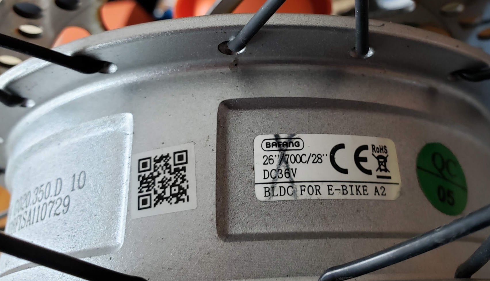
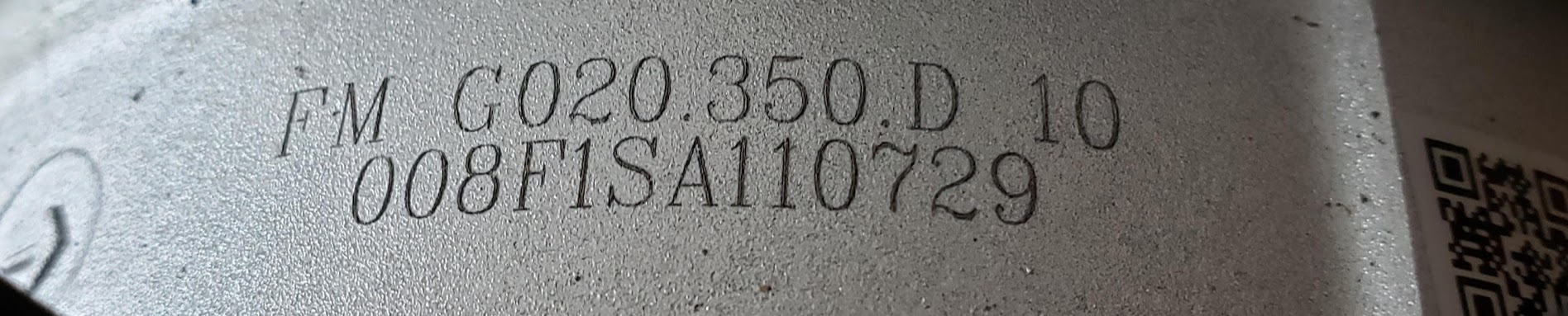
To make a definitive identification of the motor, look for the stamped model number, followed by the motor's factory issued serial number. This information may be necessary if you need to replace parts or perform other maintenance. To find information about this specific motor, google for "fm-g020-350d". Or, ask ChatGPT, or whatever tool is available as you read this.
You're likely to find information like the following, plus photos and ads for buying this model of motor, if still available:
Original BAFANG FM.G020 front motor;
Power: 350 Watt 36V;
Torque: 45 Nm;
Bottom bracket size: 100mm;
waterproof: IP65;
connector : 9-Pol Motor;
weight motor / assembled: 3,3kg
This particular motor, laced into a 26" front wheel rim, was acquired used for $25 from a social media site, pretty much sight-unseen. While it does show some signs of rough handling, the rim and spokes were straight, and the bearings and internal gears felt smooth, without noticeable play anywhere. The 9 pin male plug is typical for a BAFANG motor and is well documented elsewhere, and adapters are readily available.
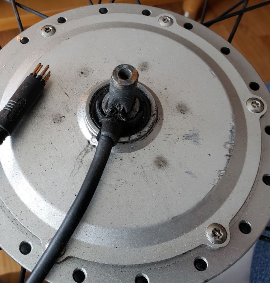
An additional intial test consisting of shorting out, in turn, of all of the motor's three phase wires revealed that the power wiring from the plug all the way through the motor was OK. A common point of failure for these motors is physical damage to the wires where they enter the motor, and a failed drive gear inside the motor. I most cases some of the internal gears are made of plastic/nylon which will melt if the motor is run too hot. This motor doesn't display any signs of either of this kind of damage. The next test is to see if the motor's three Hall sensors work correctly, and if they do, apply the correct power to the motor.

Return to Top of Page Return to Main Menu
NOTE: The first two digits of the Crystalyte model number scheme refer to the *thickness* of the motor, while the second pair (typically either 25 or 40) refers to the top speed of the motor (km/Hr @ 36V, in 26" wheel?). Therefore, a 'high' second part number means a "fast wind" motor.
Models available: HS 3540 Higher Speed,Lower Torque Note that even though it is lower in torque,it still has great hill climbing ability @ 48v expect top speeds of 45 to 50 kms per hour HT 3525 Lower Speed, Higher Torque If you live in a hilly area this is the baby for you @ 48v expect top speeds at 35 to 40 kms per hour. [older "5300" series were 6 pounds heavier] [http://www.ebikedeal.com/home_8.htm] In the summer of 2011 Crystalyte released a new series that may become a game changer, an affordably priced and rugged hub motor designed with the US market in mind. The model shaves 10 pounds off the older 5304 series, and a lower price as well. You can find the new Crystalyte motors from some dealers for as low as $280. The Hx25 is the front wheel version The Hx35 is the rear wheel version [35 = 35mm motor width] the "T" stand for Torque, faster start but more power, but less top speed The "S" stand for Speed, slower start but high speed The Hx series is like in between 4x and 5x, 9c, Bionx, all mix into two version (front and rear) of motors. ... Hx35 is a like mix in between 408, 9c, 5304, a bit of Bionx (narrow motor case that can fit 7,8, 9 freewheel easily). - the motor is lighter then both 408, 5304 - the construction is almost like 9c stamped stator (it makes the motor lighter, and cheaper to manufacture) - the magnet no longer sharped in curve, but standard straight magnet, it reduce the cost - the motor case is extremely narrow, in the flange distance, bionx is 35mm, Hx35 is 38mm, which mean no dishing necessary All Hx series is sensorless. HT2425 weight 12.60 lbs HS2440 weight 12.88 lbs HT3525 weight 16.60 lbs HS3540 weight 16.38 lbs
Motor's Key Parameters:
Crystalyte HT3525 rear hub motor, purchased from Ed Lyen, 4 Sep 2013, $380.00 USD ($349 + $31 shipping). Mounted in 406/20" spoked Odyssee rim/wheel (laced by DAS). Here is the Tringa G 's RHT3525 Motor Test Run video made by Ed Lyen for this specific motor.
@ 48v expect top speeds at 35 to 40 kms per hour (21 to 24 MPH) - on test bench, no load, full (new) battery, 23.5MPH indicated via magnetic sensor glued to hubmotor and read via Sigma 1009, programmed to 1,658mm wheel circumference (20" Schwalbe Big Apple Plus). Number of "poles ("magnet pairs" used for setting speedometer on CA): 23 is correct number. I programmed CA to use this value, and the speedometer on the CA was in "perfect" agreement with the Sigma, set to the same wheel circumference
Top speed in 26" wheel: 25-27mph @ 50V 30-40A; 31-33mph @ 72V 30-37A This motor can be used to regenerate power to the battery and provide motor braking. This sturdy motor is also known for being very quiet. Features built-in 2K thermal sensor. ES: crossbreak Sep 02, 2013 "... setup your CycleAnalyst V3 so it throttle down the motor if 90°C" is reached ... NSK bearings. Honeywell S411 hall sensors. Axle is machined for 135mm dropouts but is long enough for 175mm dropouts. Up to 7spd freewheel can fit in 135mm dropouts. A freewheel with a higher sprocket count can be installed with a spacer washer. Standard 6 bolt disk brake mount. Weight: 16.25 lbs. Color: Black. Re: New Crystalyte Motor series (HT35 / HS35 and HT24 / HS24 Postby Andje Tue Mar 08, 2011 3:29 pm Throwing this out to the wind; does anyone know what spacing we would put into the ebike.ca spoke calculator for these motors? Hub Flange Diameter/Flange Spacing is listed on the tech info, i just want to make sure this is correct before ordering spokes. HX35 Flange spacing; 1.5" 38mm HX35 Hub flange diameter; 8.75' 222mm
Return to Top of Page Return to Main Menu
Motor's Key Parameters:
UFO "H" motor series "upgrades" include:
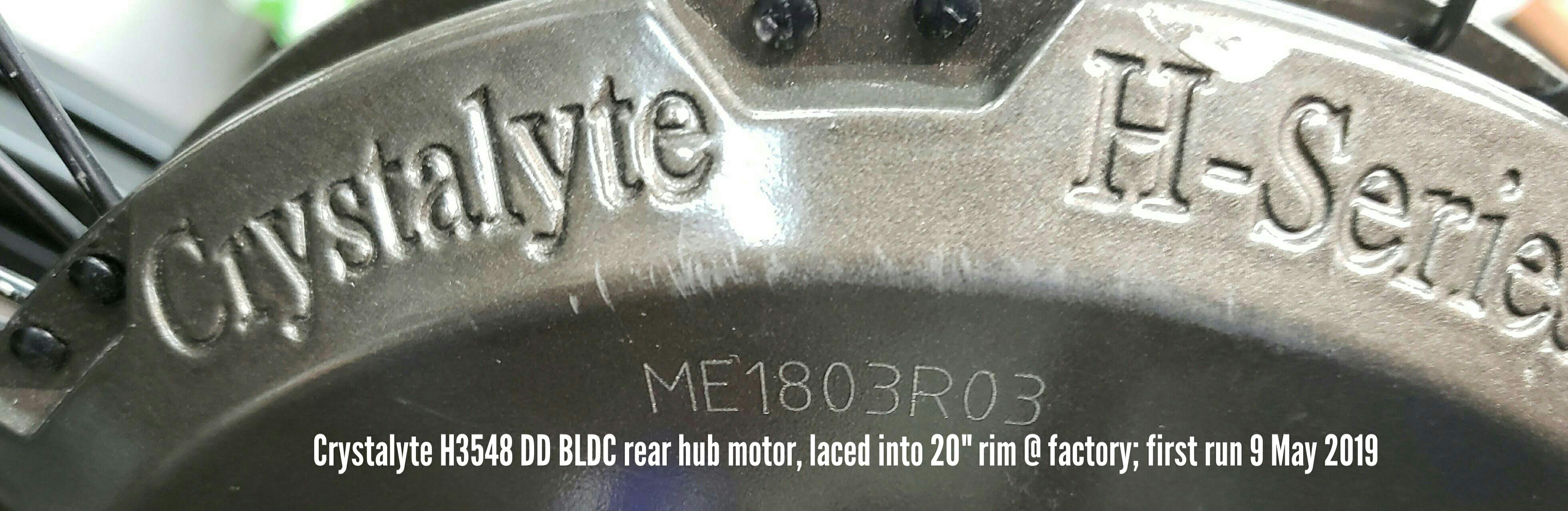
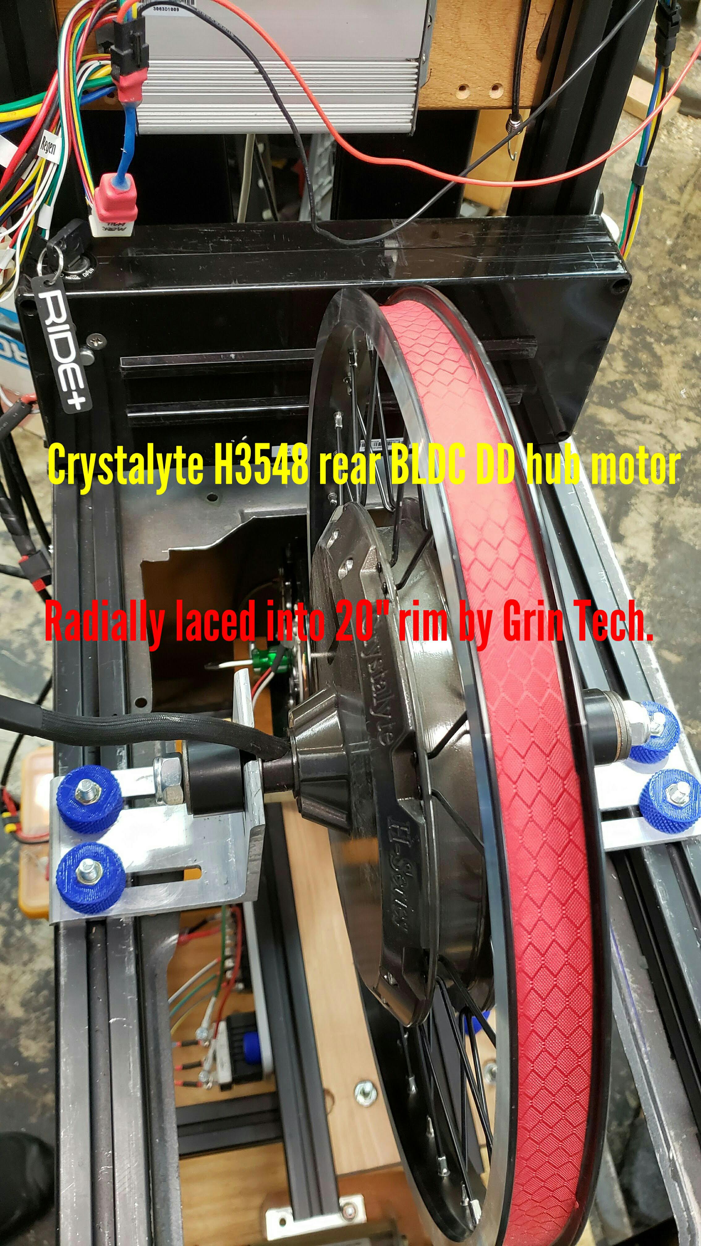
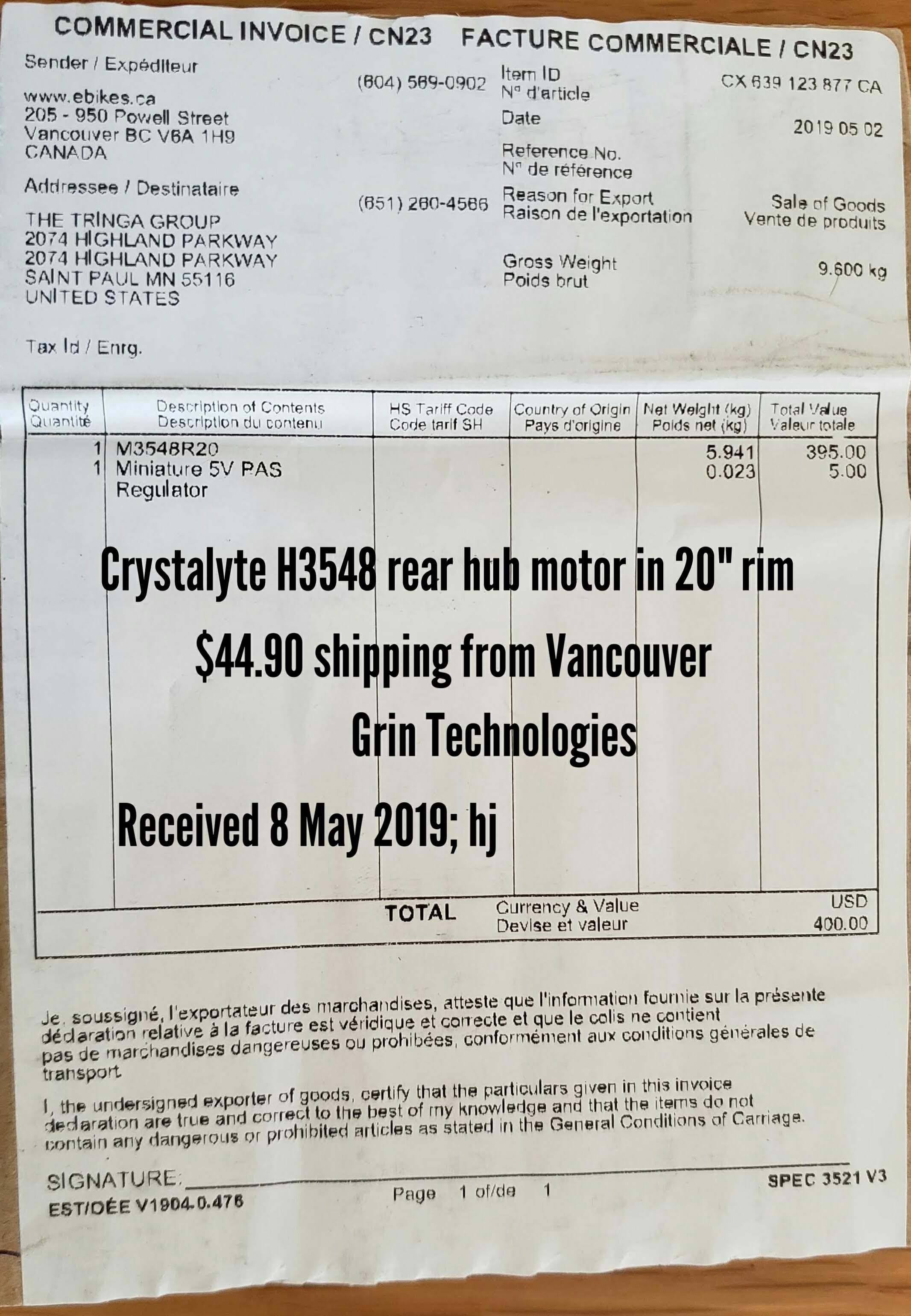
Crystalyte H3548 rear hub motor, purchased from Justin/Grin Technologies, 1 May 2019, $439.90.00 USD ($395.00 + $44.90 shipping; delivered 8 May 2019;). Mounted in 406/20" spoked Crystalyte rim/wheel (laced by Crystalyte).
Current application for this motor: eRowbike1, with Phaserunner controller.
Return to Top of Page Return to Main Menu
Our stock motor is 45KV but We can wind the motor for other KV's according your needs (if it's reasonable KV-no extra cost).
LogPost subject: Re: Weight Sensing Longboard with Inline Wheel Motors PostPosted: Thu Apr 25, 2013 11:31 pm
Return to Top of Page Return to Main Menu
The RV-100 is a small but high-power BLDC outrunner motor built by Alexey in Israel (REVOLT Motors).
Photo of the original RV-100 motor used on the SkyBike (around 2014 and later).
Showing RV-100 with machined aluminum bogie parts to fit into a 6-inch wide track.
Topview of RV-100 in 6x6 SkyRide track (by John Peterson)
Return to Top of Page Return to Main Menu
See eSkyBike Resistance Unit for more information about this application.
We are looking for the lightest and smallest mechanism that we can find to serve as a resistance unit. If this functionality can be provided by a BLDC motor run as a generator (alternator), than the question becomes "What's the smallest motor that will provide enough proportional resistance?"
Here we take an RV-100 that has a dual-ended motor shaft and try to use it as a resistance unit for the FBW eSkyBike. We're using a drill to spin the motor (CCW as seen from the motor's wire side) at ~ 1,050 RPM. The open circuit voltage potential on the other side of a 3 phase bridge rectifier is about 18 volts. Spinning the motor CW at the same RPM produces the same DC voltage on the rectifier's output side.
Return to Top of Page Return to Main Menu
A larger version of the RV-100 BLDC outrunner motor. 14 physical magnets; 7 pole pairs;
Bill James (of JPods) drills and taps one shaft end of a RV-120 to hold a wheel for direct drive on the 30' test track at Highland Pkwy. [2017]
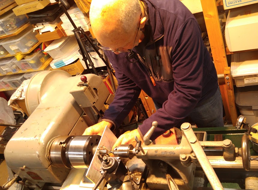
... sometimes just setting up an operation takes much longer than the operation itself.
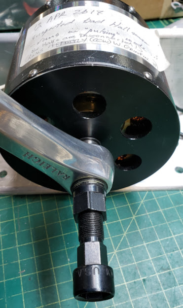
RV-120 opened up on testbench for the repair of a bad Hall Effect sensor. The replacement Hall sensor can be seen dangling near the 7 o'clock position of the motor's stator. Once soldered to the one signal and two supply wires, and having the heat shrink installed (white, black, red) over them, it will be glued into an air gap between the stator's windings. The idea is to get it as close as possible to the permanent magnets glued into the rotating outer rotor shell without actually touching them. As the magnets pass over the Hall sensor, the sensor will send to the controller a single pulse for each magnet pair passing over it. It takes a pair of magnets because the Hall sensor must 'see' one North and one South pole go by before it triggers a pulse. The magnets must be glued into the rotor so that they alternate their magnetic orientation in order for this to work correctly.
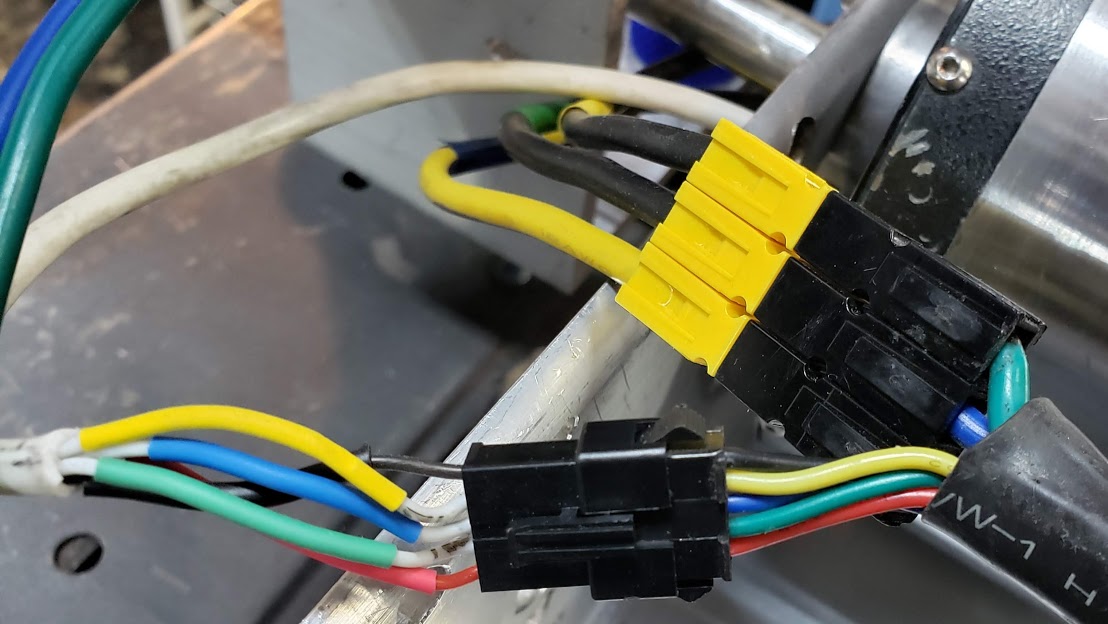
Shown in the photo below are the common RV-120 Hall sensor and phase wiring patterns. The motor connectors are on the left side, while the controller's are on the right side.
Alexey uses all black, ~12AWG silicone insulated high-strand count wires for Revolt's phase power inputs. We identify them as Blue-Green-Yellow, left to right, when looking at the motor's side from which all wires exit. In this particular motor, one black factory wire was damaged and replaced with a yellow wire, but in the "Blue" position. When the phase wires are identified this way, the motor will spin CW when connected to a standard Infineon-type BLDC controller, assuming the Hall wires are also matching this pattern. With a Grin "Grinfineon" controller, however, the BGY of the motor would need to be connected to the YBG of the controller.
The motor's Hall sensor wires shown here are mated with a Grinfineon controller's Hall connector (JST-SM-5). The red positive 5VDC power and the black negative wires are always connected to each other, regardless of the motor/controller models involved. Each Hall sensor must be powered by 5VDC, and will toggle its output pin on and off as it passes through a magnetic north and south pole pair.
Return to Top of Page Return to Main Menu
See eSkyBike Resistance Unit for more information about this application.
Here we take an RV-120 that has a dual-ended motor shaft and try to use it as a resistance unit for the FBW eSkyBike.
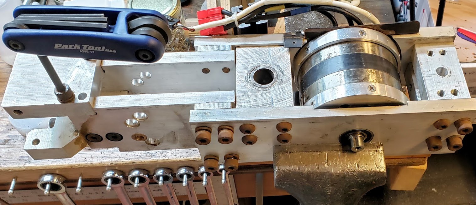
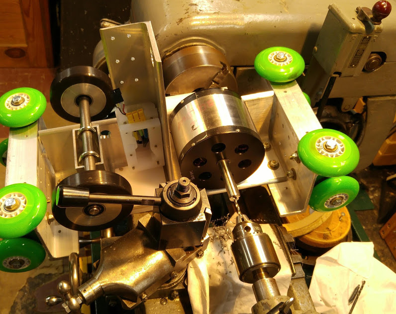
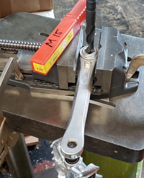
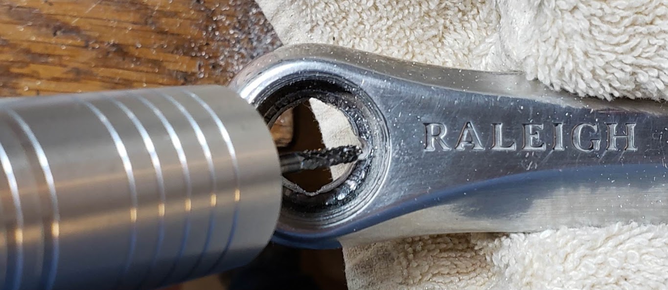
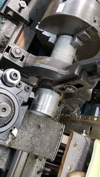
Converting the 4-sided tapered hole into a straight 15mm hole in the crank so that it can be mounted directly on the motor's main shaft. We start with the left (non-drive) side crank. The crank needs to held down firmly because we're really doing more of a milling than drilling operation here. It's aluminum and we're making a very light cut, so we can get away with it.
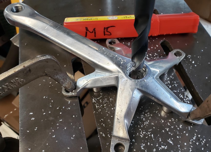
Repeating the operation for the right/drive side crank:
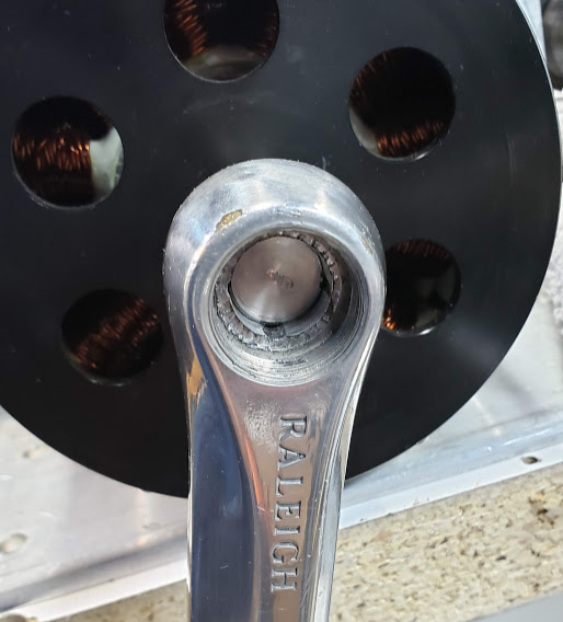
This shows that very little aluminum is removed from the crank hole to make a snug fit on the 15mm axle. Vestiges of the four square corners are left, and they will make it easier to align the cranks 180 degrees apart. We'll also use the keyways cut into the shaft to mate with the appropriate corner in the crank hole, after filing the crank out a bit. To keep the cranks fastened to the shaft, we'll either drill/tap (M8) holes into the shaft ends for use with standard bottom bracket/crank bolts, or use set screws.
Each shaft end on this particular RV-120 has a 'blind' 4mm keyway milled into it. I found two 4mm round steel pins, about 3/4" long, that fit perfectly into the milled recess on the shaft. About half of the pin sticks out above the keyway and engages a matching slot in the crank.
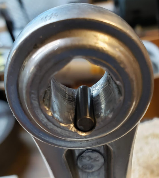
The matching slot in the crank was created by milling out one of the original square corners in the crank. Using a Foredom hand-held tool with a 1/8" carbide mill, the rough shape was created. A rat tail file was used to make it a no-wiggle push fit.
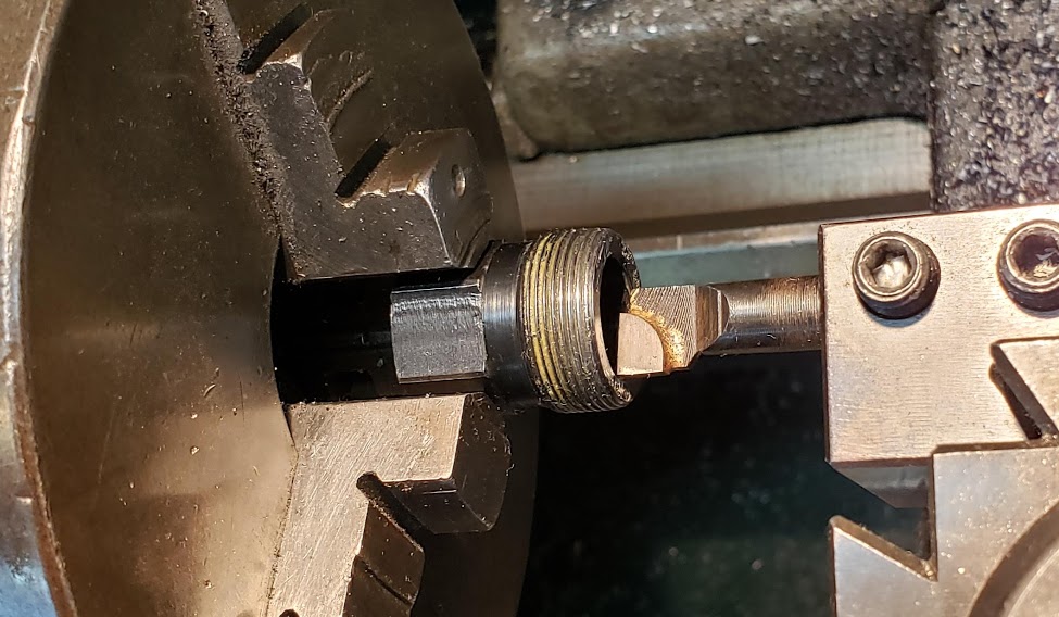
Once the crank arm was firmly tapped into place with the locking keyway pin, the next step was - of course - to remove it again for additional mods. Plan was to simply use the stock Park Tools crank removal tool I'd been using for years. Right. The stock tool is designed to fit over the bottom bracket axle as it threads into the crank. Apparently Park wasn't anticipating 15mm thick axles, because the tool's clearance stops at about 'close-but-no-cigar' (14.5mm).
Wass nich passt, wird passend gemacht. Basic engineering priciple learned at an early age from my father. Usually implemented with a hammer, but not here. Fortunately Park Tools doesn't skimp on materials when making their tools, so boring the cup out to 15.5mm didn't make anybody nervous.
Nothing like carbide edges when cutting tool steel...
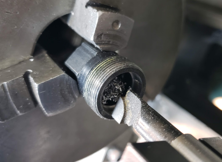
Just one little silly millimeter, and it now works! Warranty probably voided on both tool and the cranks.
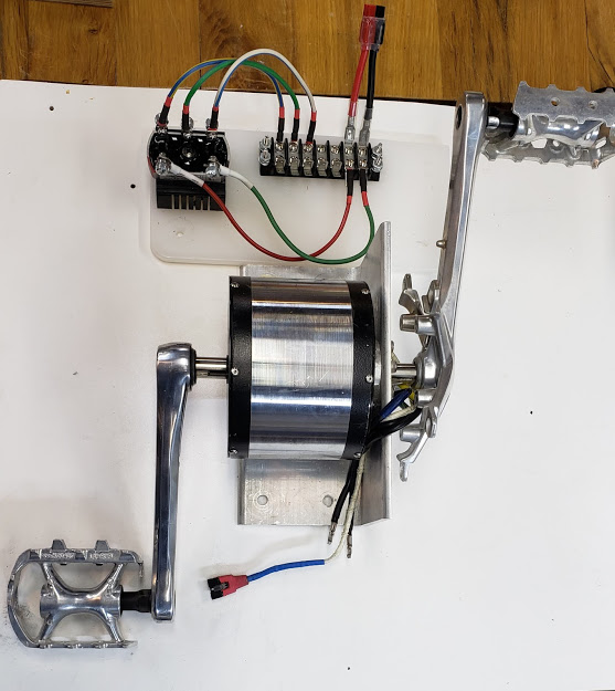
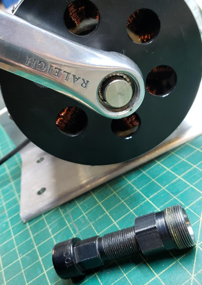
Trial positioning of RV-120 over the stock bottom bracket on the red recumbent frame. Given that this frame's boom can be adjusted for the rider's size (leg length), this can be made to work. Even given the width of the RV-120, the "Q factor" seems quite acceptable. The actual mounting method remains to be determined.
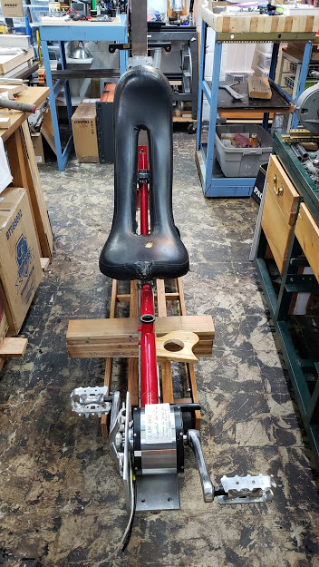
Since we already have made motor mounts for the RV-120 using 4" aluminum angle bar stock (using JPods' CNC machine), we'll simply use that to mount this motor to the red recumbent bike frame. We'll use three fastening points. The bike's adjustable boom is flipped upside down to get the angled derailleur support post out of the way. One support point will be a custom U-bolt made from scrap 1/4" all-thread (shown below), with a protective rubber sleeve to improve grip on the boom tube without scratching the paint.
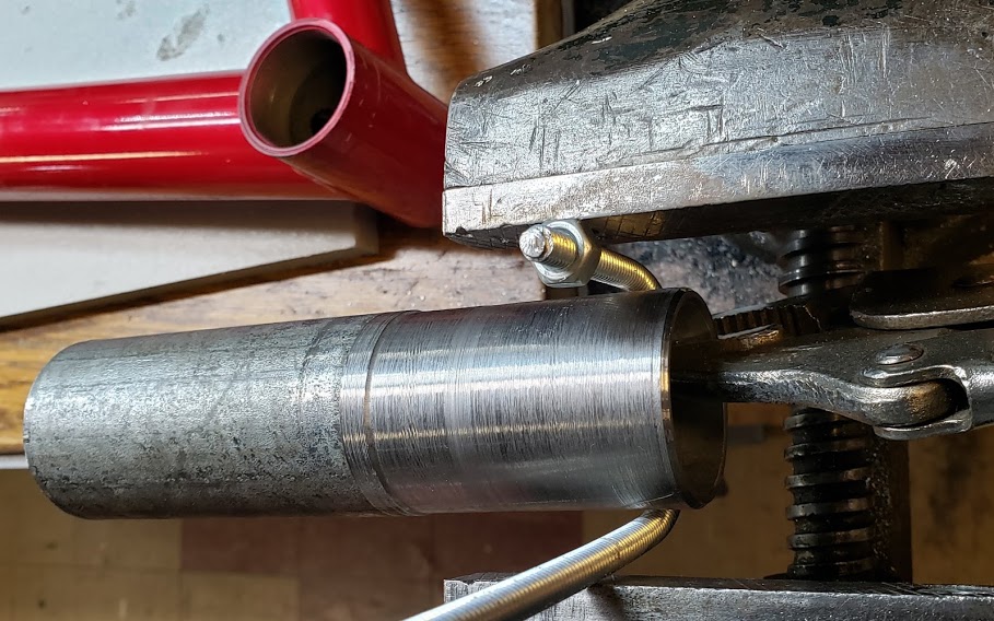
To avoid using the bike tube as a mandrel, a piece of scrap pipe was machined to the bike boom tube's outer diameter of 41mm. Not absolutely necessary, but the boom tube needs to stay perfectly round.
Return to Top of Page Return to Main Menu
See eSkyBike Resistance Unit for more information about this application.
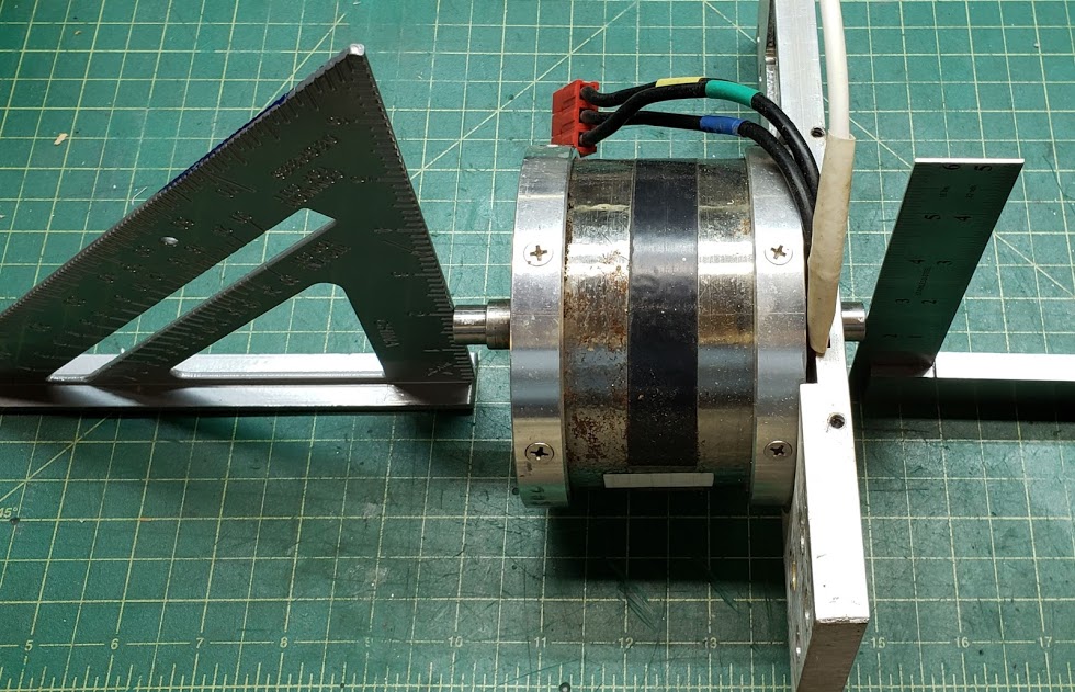
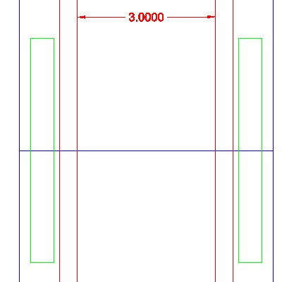
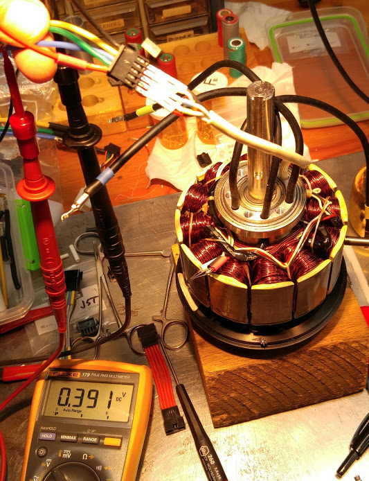
This motor was custom manufactured for us by Alexey.K of Revolt Motors for the very specific purpose of serving as a resistance unit. The goal was to achieve as low a Kv value as possible by winding the stator coils for that purpose. Its physical dimensions and shaft configuration is spelled out in this diagram.
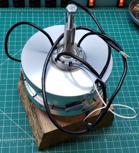
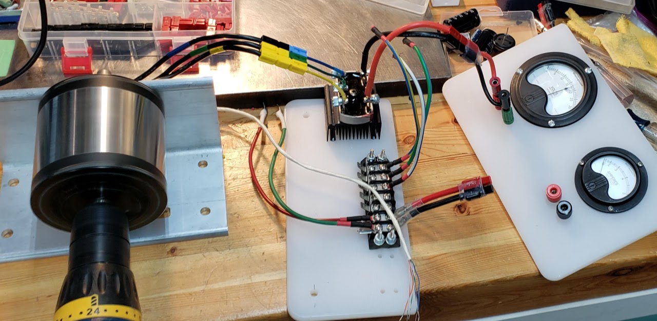
The first test was to put a crank & pedal on one shaft end of the motor and to crank it by hand while all three phase wires are shorted together. This resulted in a very smooth and 'torquey' response, with a very high degree of resistance to being turned.
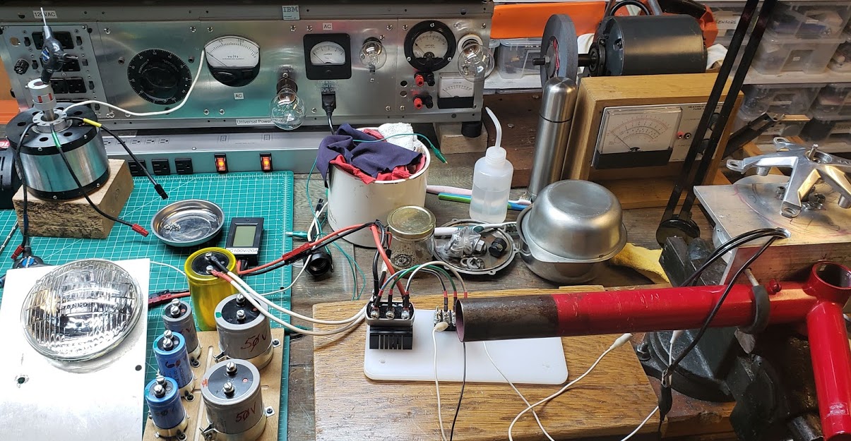
The next test was to connect the phase wires to a 3 phase bridge rectifier and drive a DC resistive load. In this case the load was a main headlight bulb from a 1967 VW beetle. The output is connected to the high beam filament, which is designed for approximately 30 watts at 12VDC. Cranking the motor by hand, which might have approached 60 RPM, resulted in an approximate 2.25 amp current at about 6 volts. A 25,000 mF capacitor was used to help stabilize the meter readings somewhat.
The next step will be to use another motor to turn this resistance unit at a consistent, measurable speed to see how close Alexey.K came to the Kv 10 target value. If in fact we were turning the motor at 60 RPM and the output was 6 volts, the Kv would be 10, so this very quick test leads to optimism.
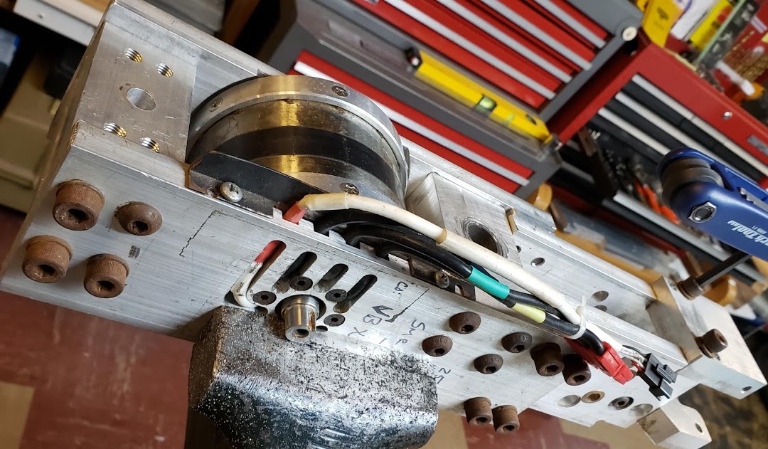
You can just see the edge of the RV-120SH mounted to the red bike's bottom bracket via a short length of 4" aluminum angle bar stock. The crank's spider (minus any chainrings) is facing upwards, with the entire assembly clamped into a vise on the workbench.
Return to Top of Page Return to Main Menu
If using the CA3 as an additional control device for the Resistance Unit, the following settings are relevant to fully enabling proportion regen, which is really what the resistance unit relies on. For instance, setting the "Throttle Min Out" to the non-default value of 0.0V may be required to pull the controller's throttle signal down into the regen range (typically below 0.8V).
| Proportional Regen with CA3 | |
|---|---|
| Ebrake Brake Out | 0.90 V |
| Throttle Input Zero Threshold | 1.00 V |
| Throttle Input Full Threshold | 4.10 V |
| Throttle Input Fault Threshold | 4.60 V |
| Throttle Output Min Out | 0.00 V |
| Throttle Output Max Out | 3.80 V |
See eSkyBike Resistance Unit for more information about this application.
Return to Top of Page Return to Main Menu
For the latest information about this motor, see the all-axle-hub-motor.html page on the manufacturer's (Justin's) site.
These motors are currently being used on the eG20 bike and the eStreetMachine.
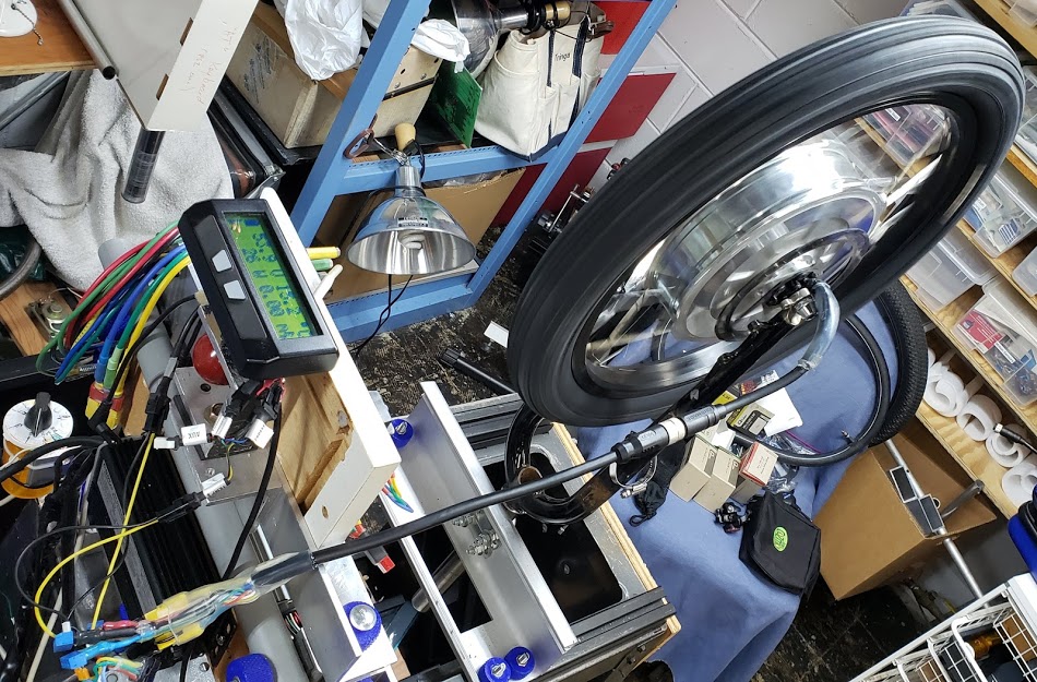
The following shows our first all-axle motor on the BogieDyno after the (failed) cable repair. While the motor spins fine, one of the Hall sensor wires is still broken so the motor won't start from a complete stop. You can tell by looking at the CA display that even though the motor is spinning freely (using 26 watts), the speed display remains at "0.00 mph". Without the three fully functioning Hall sensors, the motor doesn't output a usable speed signal. The temperature display does work however, showing 15.2 degrees Centrigrade in the cool basement.
The motor is connected to the BogieDyno using a DIY adapter to go from the 'new' L10 style to the earlier combination of Anderson PowerPole (power) and JST-SM (signals) used by the BogieDyno.
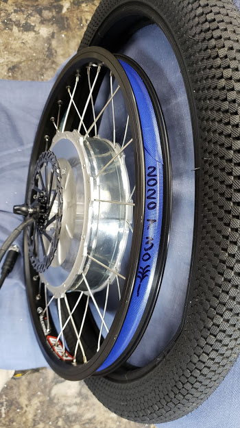
Here we can see the Grin wheel-builder's signature markings on the rim tape of our second all-axle motor, made on July 30, 2020. It's first use will be on the eG20, with a narrower 1.95" Snafu BMX tire.
Return to Top of Page Return to Main Menu
This category contains all small BLDC (in-runner or out-runner) motors. The most common models of this type that we have used are manufactured by Flipsky.
.
.
Return to Top of Page Return to Main Menu
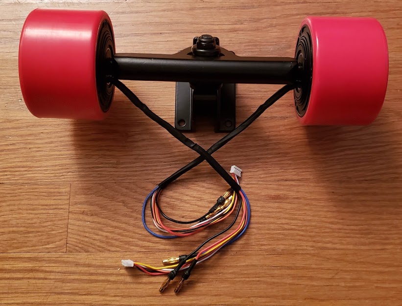
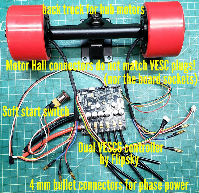
Shown below are a pair of 70mm skateboard hubmotors mounted on a "rear truck" specifically designed to accommodate hub motors. These are typical BLDC "outrunner" motors, powered via three phase wires (black, blue, and yellow) per motor. These came from the factory with 4mm male 'bullet' connectors alread affixed. For the amount of current that these motors can draw, the phase wires seem rather skimpy. These motors are also equipped with three Hall Sensors, which are powered by the controller with 5VDC plus and ground (red and black wires). This functionality is enabled via the thinner 5 wire bundle coming out of the motor, terminated by a five position JST-PH female connector. When used with a "smart" controller like the VESC, it doesn't matter in which order the Hall or phase wires are connected to the controller since the controller will determine the correct order as part of the setup process. Look under the VESC-TOOL® section for more information about this process.
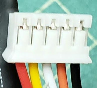
The skateboard hubmotors we're using are being delivered with a 5 pin female JST-PH connector on the signal wire bundle. These five wires consist of the standard red (positive) and black (negative) wires for suppling the 5VDC current for the Hall Sensors, and the three remaing wires (yellow, white, orange) are for the three Hall signals coming from the motor.
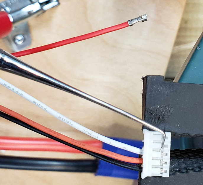
The corresponding JST-PH male header/connector socket on the controller, however, is designed to accommodate a sixth optional wire to connect to a heat sensor in the motor. Our motors don't have a heat sensor, so this shoots down a plug-and-play solution. The following photo shows the process of having to carefully remove each of the five motor wires from the five position JST plug. Carefully pry up the small plastic tab over each pin just enough so you can pull out each wire. It helps to push the wire further *into* the connector while prying up to create some space for your prying tool. Not shown is then re-inserting these same wires into a six conductor JST-PH plug, skipping the position for the temperature sensor wire. Once this is accomplished, you can simply plug the motor's signal wires into the corresponding (keyed) socket on the VESC controller.
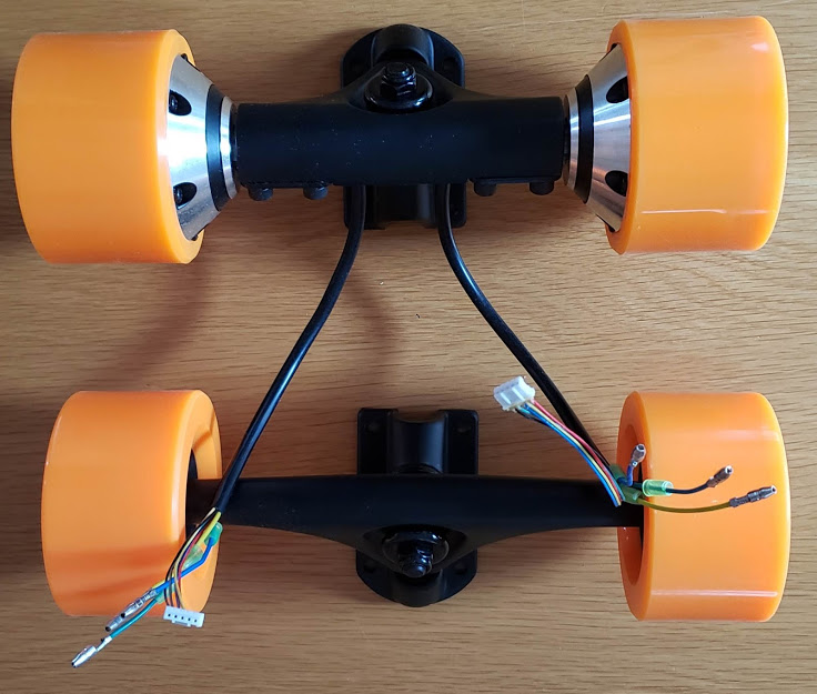
Shown below are a complete set of four 90mm (approx. 3.5") skateboard wheels mounted on trucks. Due to market trends of price and availability, JPods is standardizing on the 90mm wheel diameter format. The top two are hubmotors, and the bottom two are passive wheels. The three power phase wires for these motors feel flimsy compared to the flexible silicone insulated wires of the motors above, and the smaller bullet connectors also seem inadequate for handling any significant current flows. If drawing the full 550 watts that these motors are rated for (see specs below) while using a 6S (24 volt) battery pack, the phase wires and connectors will be carrying nearly 23 amps of DC current. (To do: measure gage of wire ... initial estimate is 18AWG, using coarse copper strands.)
The five signal wires for these motors will also need to be redone into the JST-PH-F6 connectors (see above) to connect directly to the VESC dual controller board. The manufacturer saw fit to add some hot glue where the wires enter the backs of the connectors, so this will have to be dealt with as well.
Motor specs, per vendor's ("PROMOTOR") website: (sold via Amazon, Aug 2020)
Type:brushless out runner motor
Power: 550W each motor
Speed: 70KV
Input voltage: 24V-42V (6S-10S)
Truck: 7 inch
Wheels: 9053
Color: Orange
Wheel dimension: 90mmx53mm
The photo below adds the VESC 6.6 Dual BLDC motor controller, which is functionally equivalent to a pair of identical single VESC controllers connected to each other via a CANBUS communication protocol. This combination of two controllers on a single PCB simplifies the task of having both motors controlled by a single throttle input. For this project we'll be standardizing on 83mm diameter hubmotors, which look just like these but are larger.
When used with a VESC controller, the 83mm in-wheel hubmotors we're using on the skateboard bogies do not require having their phase (power) wires individually identified. You might encounter some motors and/or controllers in which the phase wires have been identified as being either blue, yellow, or green. This was likely done for testing with other BLDC controllers where this color sequencing was necessary. The "smart" controllers like the VESC series (and Grin Phaserunner) will internally map the correct sequencing of these phase wires when the controller is matched to a specific motor via the 'autodetect' process (see under VESC controllers, Motor Detection). Since we've standardized on the VESC controllers, this means you can safely ignore color markings on phase wires as long as you go through the appropriate motor detection process each time you change *either* the motor or controller combination! This also applies to the color-coded Hall Sensor signal wires, but NOT to the red and black voltage supply wires, which must *always* be correctly connected. Confirm this visually by matching wire colors to the silkscreen labeling next to the connector on the controller board.