See also the CAv3 manual under "PAS -- Operation".
The CA takes the torque voltage input from the INA module and subtracts an offset value to normalize the voltage relative to the zero-torque signal level. See PASD-> Zero Torq. [This was "Trq->TrqOffst" in previous firmware.]
It then multiplies this voltage by a decimal number to arrive at a specific torque (weight) on any desired linear (proportional) scale. The CA, designed for global use, displays the result in units of the newton meter (Nm) torque scale. Using this torque value with the greater of 55rpm or actual rider cadence (strokes per minute/SPM), it calculates a baseline 1x 'Assist Watts'. See PASD-> Trq Scale. [This was "Trq->TrqScale" in previous firmware.]
It then subtracts Trq->AsstStart from this baseline assist power and multiplies the result by Trq->AsstFactr to determine the final assist level. The determined assist level is used to control the motor using the Power PID controller which is configured by PLim->MaxPower and Plim->WGain.
PASD->SETUP PASD-> Sensr Type PASD-> PAS Poles PASD-> Signl Type PASD-> Dir Plrty PASD-> Trq Scale PASD-> Zero Torq
PAS->SETUP PAS-> PAS Mode PAS-> Strt Level PAS-> Scale Factr PAS-> Asst Avg PAS-> Strt Thrsh PAS-> Stop Thrsh
teklektik's key parameters for PAS settings on CA v3.12 (late 2018): These settings are the key settings (per Teklektik) to determine the performance tuning of any PAS/Torque ebike setup, once the hardware settings are correctly set up.
ThrI->CntrlMode = for us this will almost always be "Pass-Thru" (default) ThrO ThrO->DownRate = ThrO->UpRate = ThrO->PASRate = ThrO->FastRate = ThrO->FastThrsh= PLim->MaxCurrent = PLim->MaxPower = PLim->AGain = PLim->WGain =
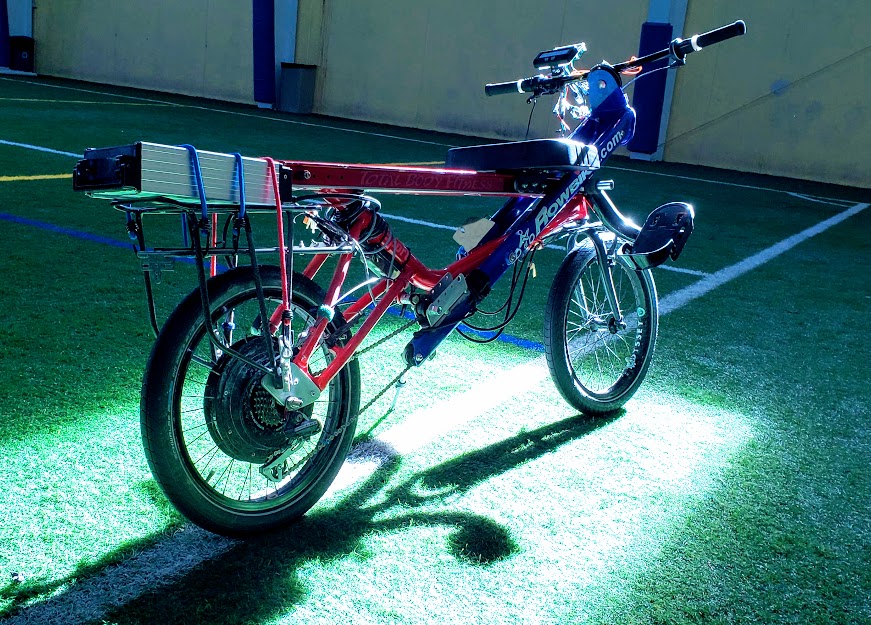
The "SETUP PAS DEVICE" preview screen shows the state of both of the PAS sensor inputs, the current (live) torque voltage signal level, and the corresponding 'scaled' Nm value. A long right button press 'enters' the group of properties that are related to the PAS device being used. Make sure you haven't selected any of the "Basic" PAS modes, because none of them support the TORQUE input signal.
The RPM ("P") and DIR ("D") glyphs ("crosses") indicate the current digital status of either high or low (0|5VDC) for each of these inputs. If the bar of the cross is up, the input is at +5V, and when down it is at 0V. When the inputs are pulsed the bars appear to move up and down.
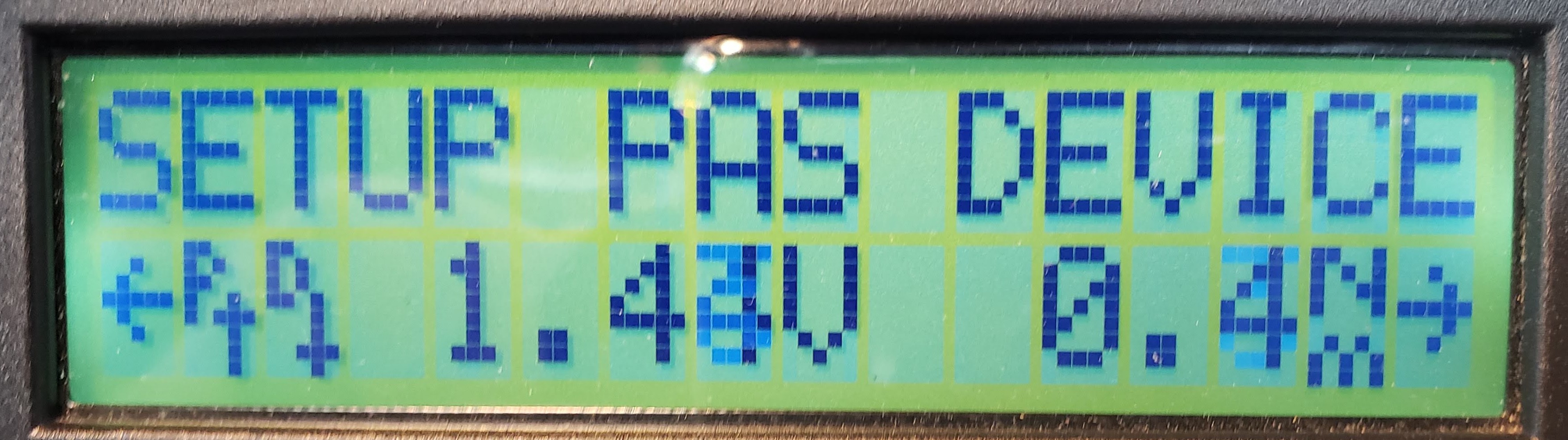
Chooser to select the type of PAS sensor installed.
Custm TRQ:
Select "Custm TRQ" if the sensor is either a custom device type with unique settings (like the eRowbike1 with INA) or one of the preconfigured types below.
These are sensors for known device types. These selections cause preconfigured defaults to be copied into place for other settings in this category. The sensor type remains as selected if those other defaults remain unmodified, however, changing a default setting will change this sensor type to 'Custm TRQ'. Downloading one of these preconfigured sensor types from the Setup Utility will similarly set other settings to the associated preconfigured defaults exactly as if the preconfigured type had just been selected by CA Console Setup, overriding the other settings that may have been present in the Setup Utility.
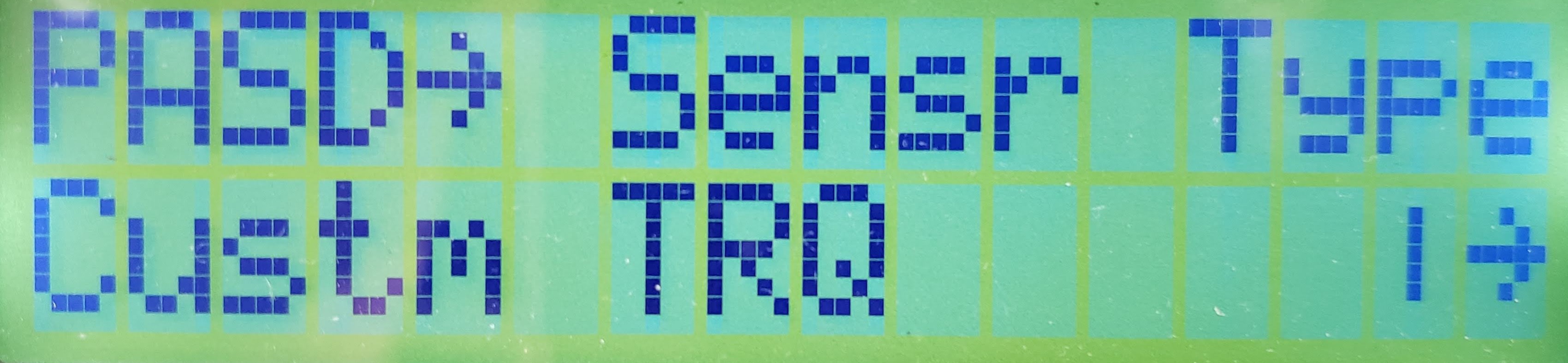
Poles (Integer)
This is the number of pulses received by the CA's RPM (yellow) wire on the CA-PAS plug input which constitutes one human power 'cycle'. On a normal pedal bike, this corresponds to one full rotation of the pedal sensor, which would normally be one revolution of the pedals/cranks/chainring assembly. On the erowbike1 it will be the arbitrary number of magnets on the custom-built PAS pickup unit used to track the back-and-forth movement of the powerlever. The bike RPM or erowbike1 strokes per minute (SPM) are the "cadence" calculated and displayed by the CA.
In addition to calculating cadence, the CA uses this number to more effectively stop and start the motor assist via the PAS-> Strt Thrsh and PAS-> Stop Thrsh settings below.
For 'off-the-shelf' PAS sensors, this will be a predetermined number. It is 8 for a THUN sensor and 12 for a TDCM sensor. For common Chinese magnet ring PAS disks this number can vary from 5 all the way to 16 in some cases.
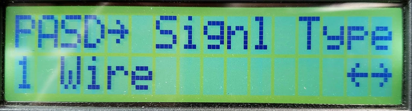
1|2 wire
This setting determines the number of input wires that carry cadence pulses so the CA can best use the available information. The type can be determined by examining the arrows next to the 'PD' on the SETUP PAS DEVICE preview screen as the crank is slowly turned. On a single wire sensor only the P arrow will changes, while on a 2 wire sensor both the P and D arrows will flip UP/DOWN. 1 Wire: Cadence pulses appear on the RPM input with no simultaneous change to the DIR input. 2 Wire: Quadrature encoded cadence pulses appear on both RPM and DIR inputs. If using a 3rd party PAS sensor with just one wire to the RPM pin of the CA, then select the 1-wire choice.
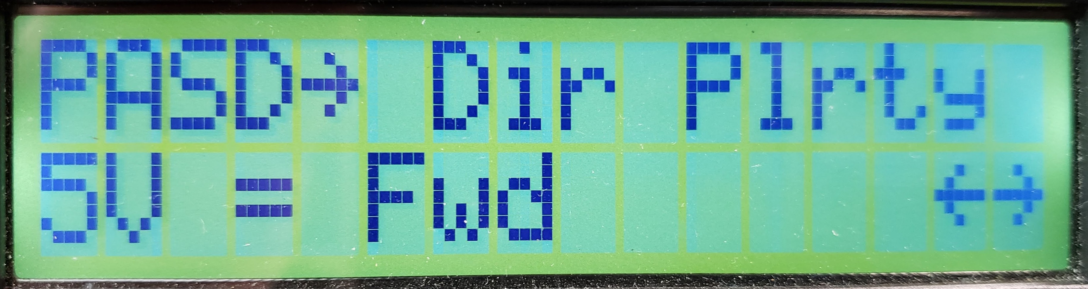
5V=FWD|REV
This controls whether the +5V on the "Dir" pin is considered forward or reverse "pedaling". For the erowbike1, this must be set so that the power lever being pulled back by the rider equates to pedaling forward. Since no assist is provided if the system thinks the pedals are going backward, we must make sure this setting is correct. If the Dir pin is not connected, then it should be set to 5V = Fwd. For a quadrature encoded device, you will tell from trial and error if this needs to be set to FWD or REV for your encoder setup.
During prototyping and testing, the thing to do is leave the Dir pin [Blue wire on CA's PAS plug] disconnected. The CA's circuit will pull the DIR pin high (+5V), and if we set it to "5V=FWD", the system will think that any PAS activity qualifies as "forward", and assist will be provided according to other parameters' settings.
Tek says: "Here we have the difference between the physical signals and the logical interpretation of the sensor signals. The P & D arrows reflect the hardware signals and no setting can change the physical hardware. The purpose of PASD->Dir Plrty setting is to adjust the logical idea of 'Forward Pedaling' to be correct as appropriate whatever the hardware signal." There you go.
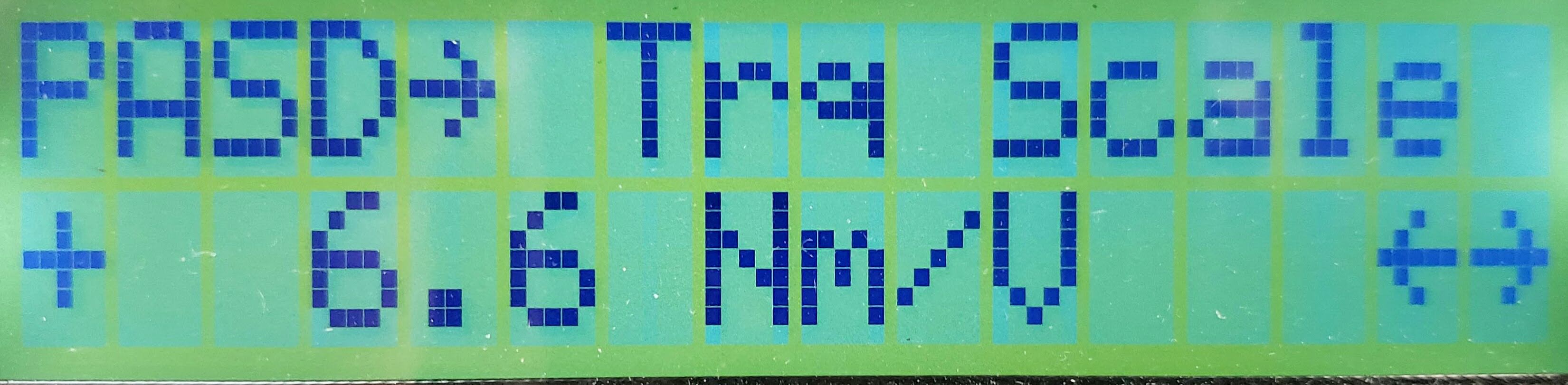
Nm/Volt (decimal)
This option is visible only when a PAS device (PASD) has been selected that includes a torque sensor. This includes the "Custm TRQ" device selection which we are using here for the eRowBike1.
While the CA's stock firmware specifies this setting in newton meters per volt (Nm/Volt), it could just as easily be scaled using foot-pounds per volt, or even just pounds per volt. The "scale" here simply refers to the units being used to display the current amount of torque (weight) that is being applied to the handlebars. The handlebars are acting as a digital scale, and the weight they're measuring can be expressed in any units of weight we want. For American (US) riders the most useful scale will be using the pound as the unit. The essential thing to remember that any amount of weight placed on the handlebars (either by pushing or pulling) will change the signal voltage sent from the INA to the CA. Since the correlation between the weight/torque applied and the voltage signal is linear and proportional, this "scale" setting is simply a multiplier that defines the units for the display. Unfortunately we aren't yet able to edit the display to reflect whichever arbitrary units of weight that we are using, other than Nm.
The higher the decimal value used for this setting, the more "sensitive" the handlebars will *appear* to be. The reason for this is that while any particular weight placed on the handlebars will cause the same increase in torque signal voltage (assuming the INA is set for the same amount of gain), the number of weight units displayed on the CA screen will be correspondingly higher. If we set "PASD-> Trq Scale" to 5.0 Nm/Volt, the CA will display about 18Nm when the rider maxes out the pull on the power lever. If we triple the scale value to 15.0 Nm/Volt, the same amount of pull would result in a display of 54 Nm. Due to configuration of the INA, the "maximum" pull on the power lever results in a torque voltage signal of 4.99 volts. Pulling harder may deflect the handlebars some more, but (due to saturation) the INA's output signal voltage will not rise above 4.99V.
Since we want to read the torque display in pound units, we'll calibrate the handlebars by applying a known number of pounds of pull, and then adjusting the "scale" setting until the CA display matches the true weight in pounds. We'll simply ignore the "Nm" designation of units and undertand that the number is actually "pounds". Note that the angle of pull on the handlebar makes a dramatic difference in the measured torque. This is due to the fact that the strain gages are specifically mounted on the handlebars to measure the pull of a rider of 'average' height. Pulling the handlebars at different angles with exactly the same amount of force will result in different amounts of assist.
Setting this accurately is necessary only to calculate an accurate 'human Watts' value for display. If it is inaccurate, things generally work fine and exactly the same power assist and operation can be achieved -- just with slightly altered Setup values. Offsetting the "true" torque by some factor can be compensated by a similar inverse adjustment in the 'assist factor'. Getting the torque scaling accurate is necessary to make the human power display reliable, but not necessary if you don't care about HWatts and just want the right assist.
For pedal-based devices that sense torque on only one side of the crank, the value should be doubled to simulate the net left and right pedal torques. The value can be set either positive or negative and is populated automatically when a known sensor type is selected (like the THUN and TDCM). For TDCM sensors, additional tuning is required and may be initially guesstimated as the number of teeth on the front chainring. So a 44T chainring would be about 44 Nm/V. On the eSkybike using the TDCM, we used Trq-Scale value of 42 to achieve reasonable results.
The torque scaling can also be dynamically (while riding) adjusted with an external 5K pot as 'Assist level'. A switch, like the Grin 3-way handlebar switch can also be used.
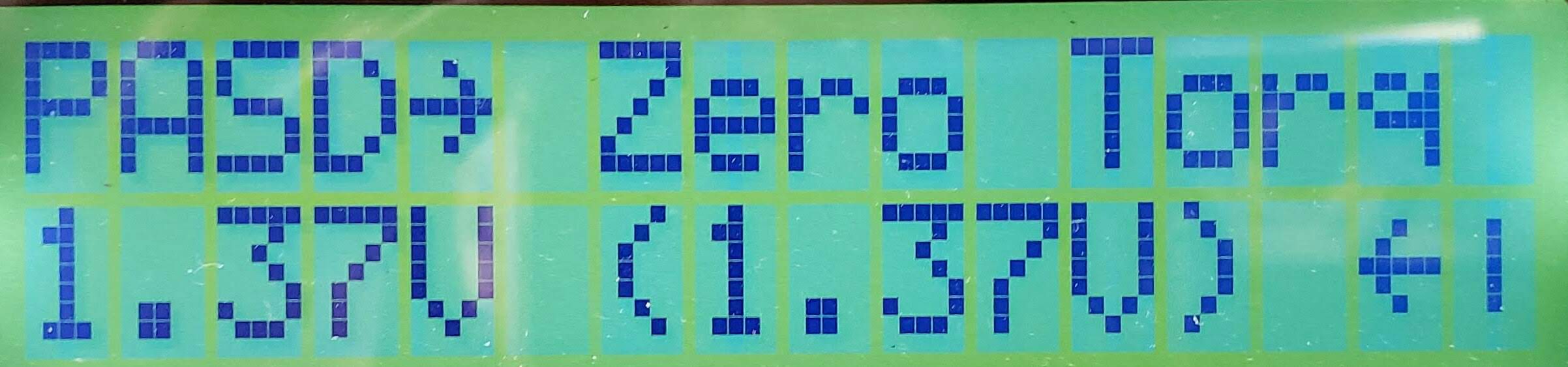
Volts (decimal)
Think of this as the "Tare" button on a digital scale -- it 'zeroes out' the scale to account for whatever empty container is already on the scale. In the case of the erowbike1, whenever new accessories are placed on the handlebars this number will need to be changed, since the handlebars are effectively a very sensitive digital scale.
The configured zero-torque offset voltage and the present *live* torque voltage (inside the parentheses) are both displayed. The right CA button should be pressed and held for a second or so with the handlebars (pedals) unloaded (zero torque). This results in a new zero-torque voltage from the present live torque voltage. This voltage is displayed when the button is released. It's a bit tricky to get this value set accurately on the erowbike1 since the CA is mounted to the handlebars, so it's a bit like pressing the "Tare" button on a scale while your thumb is on the scale. Also, some magnetostrictive torque sensors (like THUN and NCTE) don't return to the same zero point very well after high torque excursions. The steel erowbike1 handlebars appear to be very stable in this regard. Obviously, this option appears on the menu only if you have selected a torque-capable sensor type.
PAS->SETUP PAS-> PAS Mode PAS-> Strt Level PAS-> Asst Avg PAS-> Strt Thrsh PAS-> Stop Thrsh

The PAS CONFIG settings configure how the ebike's assist system responds to various rider inputs. These input devices might be a power lever, a TruRow drive, or a set of pedals, or some combination of these and other sensing devices. Sensors on the input devices supply the signals which are then processed by the CA firmware according to the settings detailed in this section. The system needs to be tuned both to meet the rider's preferences and safety. The settings (parameters) cover both cadence sensing (PAS) as well as torque signals. The use of an Auxiliary Input device (like the "Aux Pot") is recommended to increase or decrease the assist level on the fly (while riding).
The "SETUP PAS" preview screen shows the currently selected PAS Mode, and when the Mode is "Torque", it also displays the Scale Fctr.
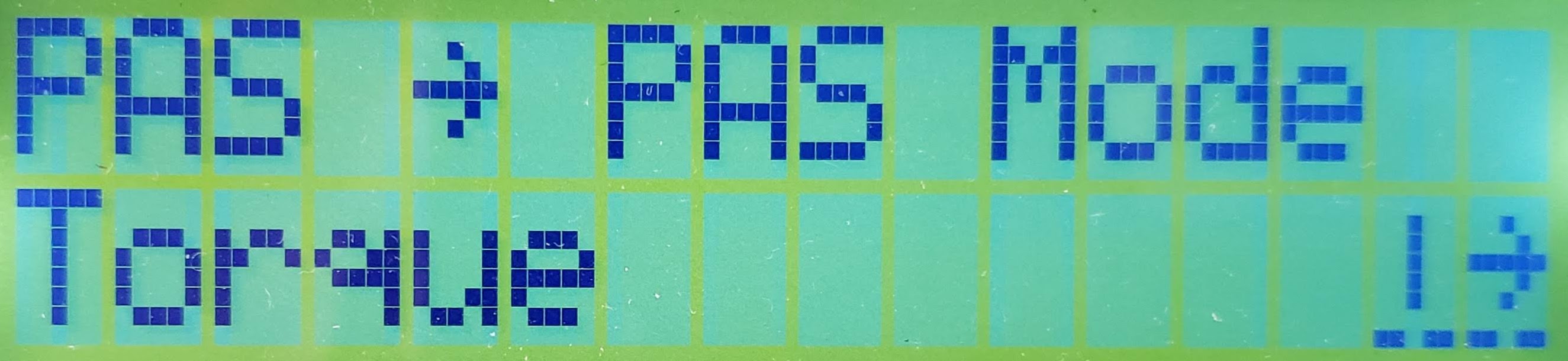
Chooser to select the type of PAS Mode to be used.
Here we select which pedal assist system (PAS) mode is used for the erowbike1, from the following options. Since we rely on the torque applied to the handlebars as a primary input, we'll select a mode which utilizes torque. These modes have seen numerous changes as the firmware has progressed.
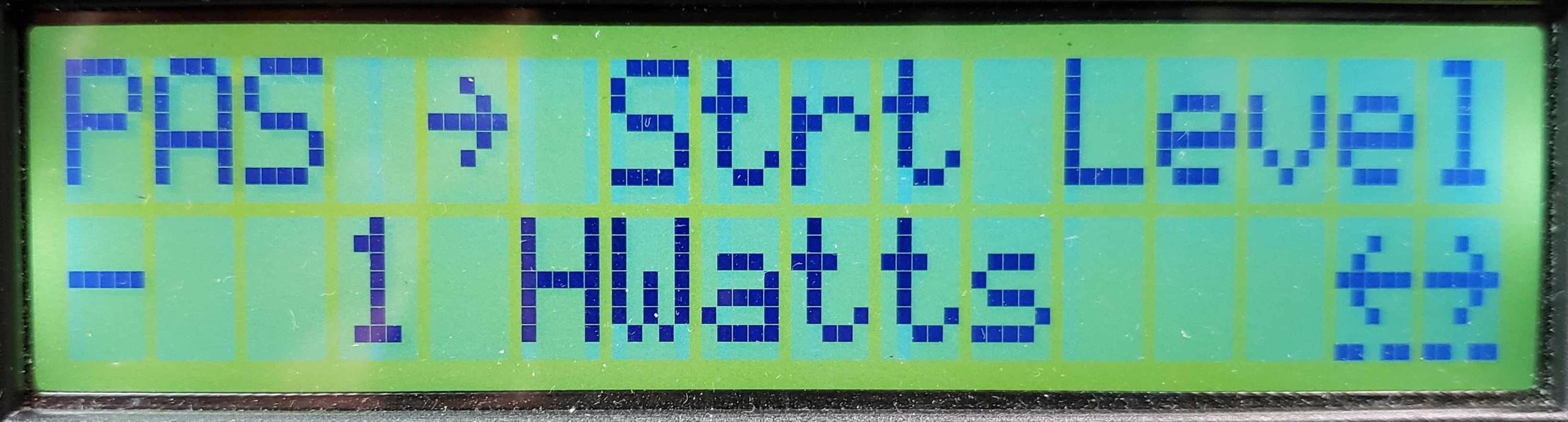
HWatts (integer)
Remember that the meaning of this setting depends on the PAS mode currently selected!
For the "TorqPAS" mode we're using for the erowbike1, I think this corresponds to the previous "Trq->AsstStart" (Torque Assist Start Threshhold) in a prior CA firmware version??
The minimum number of (human) watts the erowbike1 rider must be producing before *any* assist is provided by the motor. If, for instance, it is set to 100 watts, then any time you are rowing or pedaling lightly you won't get any assist, and only when your human effort exceeds 100W will the motor torque kick in. For the most satisfying rider experience, we may well want to provide assistance as soon as the rider begins to pull on the handlebars. At this point the rider hasn't yet produced any human watts, since human watts is based not only on torque but also on the rearward movement of the power lever (or rotation of the pedals). Consequently, we're likely to keep this number very low -- possibly even negative, which the system will allow. Grin says "If you want the motor to exactly scale the human power even at minimal pedal force, then this should be set to 0 watts."
HWatts are always calculated and displayed accurately, assuming the torque and cadence sensors are scaled accurately. The actual assist power provided by the erowbike1, however, is not always based on this 'true' HWatts. The assist calculation takes the *maximum* of either (true rider cadence/PAS RPM) or (55 RPM). This is done to give some extra e-assist on the 'getaway' where cadence/RPM is zero or very low. HWatts is a separate calculation that does not involve this '55rpm' modification and so is always accurate. Above 55 PAS RPM, the two calculations have the same result. (We are ignoring Trq->AsstStart here.)
For the eSkybike, I finally stumbled on this as a "key" setting: the "Trq->AsstStart" (Torque Assist Start Threshhold) was defaulting to to +100 watts. This setting is defined as the amount of human power (in watts) that needs to be contributed before the electric assist kicks in. We were never reaching this minimum of 100 watts human power, so the throttle signal calculated by the CA never went over zero. The manual says this value can be stated as a negative number to make the assist kick in much sooner -- without really depending on human power to be measured first. Rather than keeping this a negative number, experience is showing us that it's much better (smoother acceleration) to increase the "human watts" produced by raising the resistance to the pedals being rotated. For the erowbike1 with the INA this would translate into a higher assist level. This suggests that it's important to get the HUMAN WATTS part of the system correctly dialed in before doing other tuning.
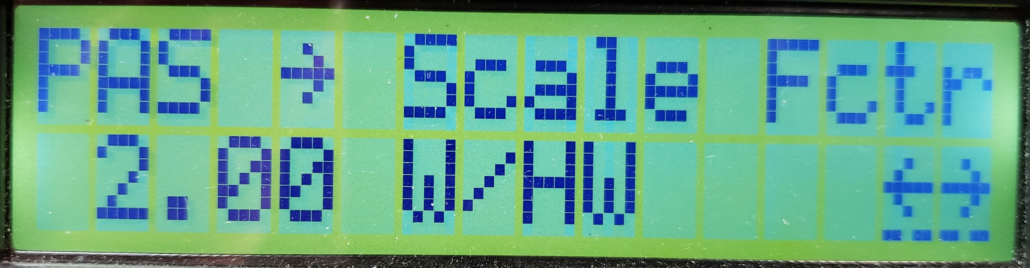
Watts/HWatts (decimal)
This value should be read as the "number of motor assist watts added for each human watt provided by the rider". It will likely be a small integer, unless you need to do some very fine tuning.
The meaning of this setting depends on the selected PAS Mode. When set to "Torque," as we do for the erowbike1, the PAS "Scale Fctr" is the proportional assistance multiplier that is provided based on your human power input. For instance, a setting of 2.00 W/HW means the electrical motor watts will be double the applied human watts.
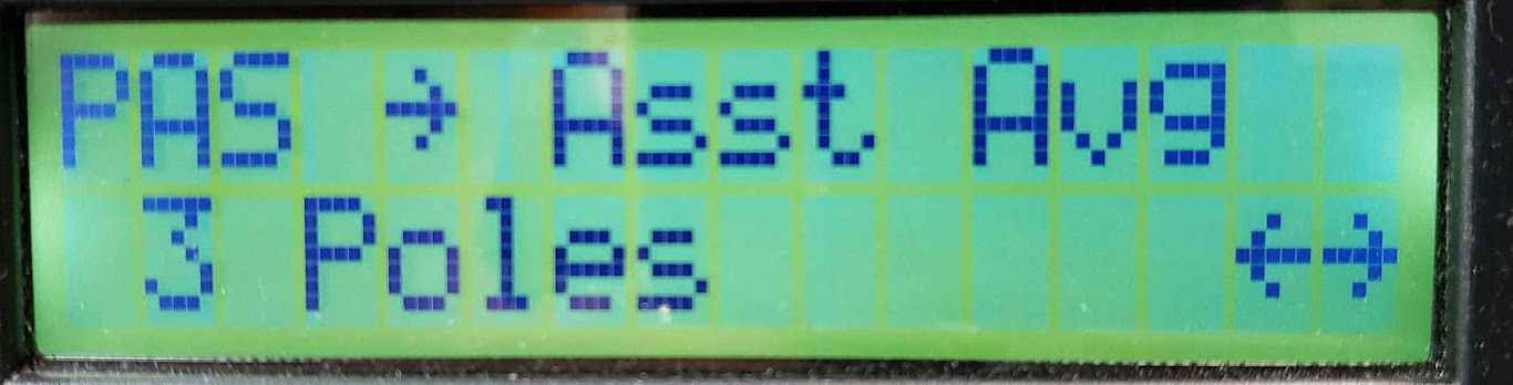
Poles (Integer)
Tuning Hint: Higher values yield smoother power assist at the cost of slower response to changes in human effort.
Because human power input on any type of bike is usually not very smooth or consistent, it's often not a good idea to have the motor assist completely mirror the rider's input. The human pedal torque undulates with each turn of the cranks so the signal should be averaged to prevent corresponding pulses of motor torque. While the rowing stroke of the erowbike1 is completely different from standard bike pedal rotation, it may still be desirable to smooth the power curve delivered by the motor in response to variations in the power stroke, including the cadence (strokes per minute, SPM).
Even though the value for this "Asst Avg" setting is specified in "Poles", it really represents the number of *pulses* received by the CA over which the torque signal used for calculating the level of motor assist is averaged. A "pulse" is measured by the voltage on the RPM (yellow) wire on the CA-PAS plug being pulled low (grounded) momentarily. Because the source of the pulse is often a magnet acting on a switch, the term pole is customary.
For a pedal powered bike, the number of pulses represents the amount of pedal rotation. PAS/cadence sensors typically rely on one or more rotating magnets ("Poles") placed in a circular pattern next to the chainring. As the rider pedals the bike, a sensor attached to the bike's frame detects these magnets as they pass by the sensor, sending one pulse to the CA per magnet encountered. Knowing the number of magnets being used, the CA then calculates the RPM's at which the rider is rotating the pedals. This is much like the common method used by bike 'computers' to display the bike's speed and distance traveled by counting the number of times a single magnet attached to a front wheel spoke passes by a sensor on the bike's frame.
For the erowbike1, we have full control over designing a PAS pickup unit that utilizes an appropriate number of poles (magnets) [TBD]. A complete stroke of the powerlever will cover approximately 90 degrees of an arc, so a minimum of six magnets will probably provide sufficient data points for whatever averaging will be necessary. In addition, the PAS sensor's input is necessary to allow the CA to calculate the amount of human power (HWatts) being contributed by the rider. Power is the result of a measured amount of torque over a measured amount of time or distance.
This "Asst Avg" setting is populated automatically when a known sensor type is selected.
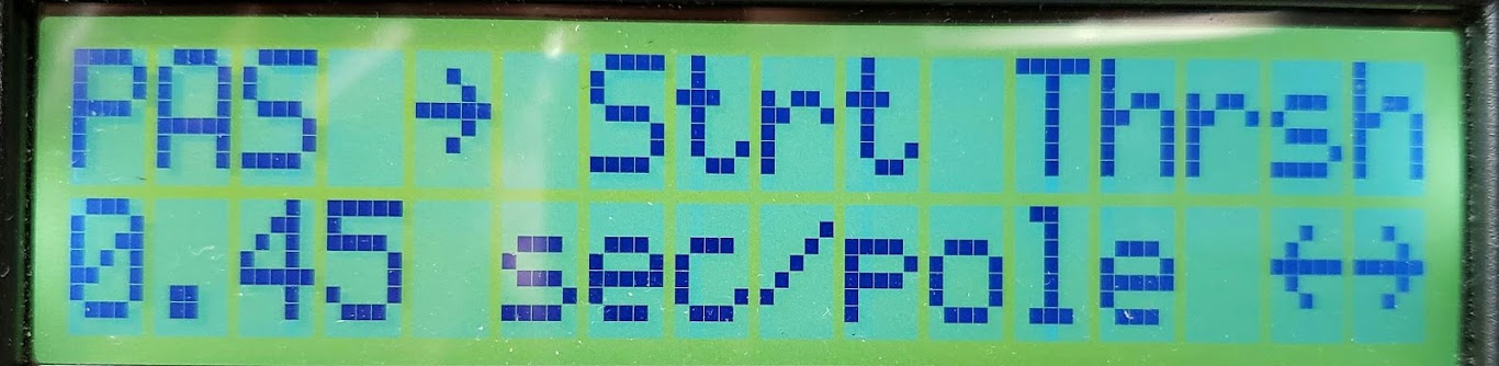
sec/pole: Seconds per pole (Decimal)
Tuning Hint: Since we're likely to want a very responsive start on the erowbike1, we probably want this value to be as low as possible.
Sets the shortest time in seconds before the CA begins to activate any motor assist. No assist is provided in any PAS mode *until* the CA senses that the rider is actually 'pedaling' (or providing some human power input). This setting, scaled in seconds, is a forced waiting period during which nothing happens until the CA receives one or more pulses ("poles") via the yellow "RPM" wire in the CA-PAS plug.
This is considered a 'safety feature' because it prevents the ebike from taking off on its own if the rider were providing only torque but no movement. This could happen if the rider were simply standing on the pedals, for instance. The erowbike1 could begin moving under motor power if someone simply grabbed the handlebars.
If "Strt Thrsh" is set to a short period, assist will begin sooner when starting from a standstill, but there will also be a longer delay before the motor cuts out if human power input stops within a single stroke (revolution on a pedal type bike). By using more poles (magnets) in the PAS sensor (resulting in the magnets being closer together), the lower the time value can safely be for this setting. Sensors with more poles give brisker response because the CA gets sensor pulses more quickly, and can use shorter threshold times.
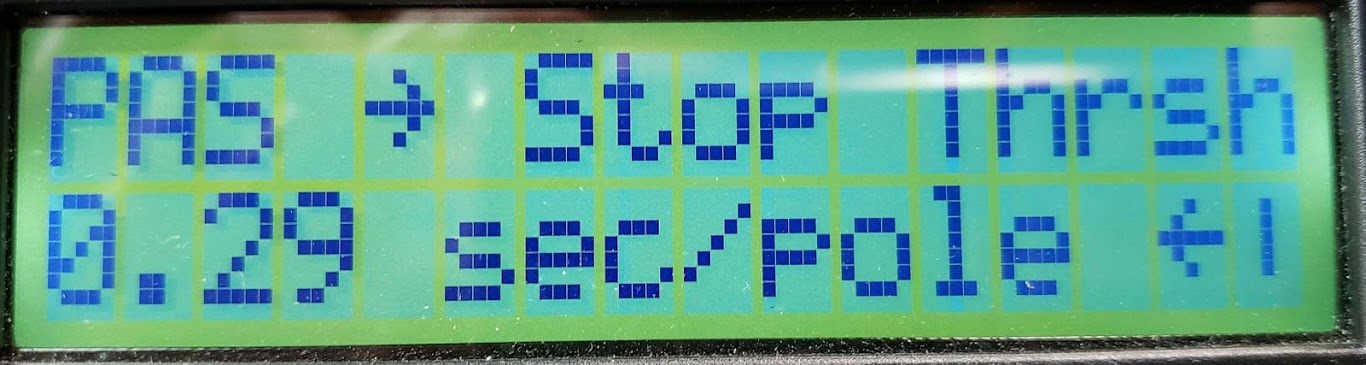
sec/pole: Seconds per pole (Decimal)
Tuning Hint: Sensible values are usually between half and the same as the Strt Thrsh value.
After the first complete crank revolution, sets the minimum time that must be maintained between pedal sensing events for the CA to assume that the rider is still pedaling. If the time between pedal events is longer than this threshold, the CA will assume that pedaling has stopped and will cease power assist. Short values result in a more immediate cutout in power, while longer values allow for pedal assist even at slow pedal speeds.
There are at least 60 CA3 firmware settings that can dramatically affect the behavior of the erowbike1. Obtaining the desired behavior lies somewhere between settings that result in NOTHING happening and settings that make the bike SUDDENLY take off with 1,500 watts of high torque power and accelerate to top speed. Other than obviously having the bike in a test stand (wheels off the ground) while obtaining the desired settings, the following are tips to get to these settings sooner, safer, and saner.
Before attempting to tune any software settings, make sure all hardware is in fact working as intended. This includes the battery (traction pack) providing a voltage level above LVC, and the CA3 having the appropriate firmware loaded. For the erowbike1 running with the 'skateboard' firmware, the torque input for the forward signal (INA/handlebars) must be supplying a proportional positive voltage signal, while the rearward signal provided by a 5K pot must counterbalance that signal to allow stop-and-go behavior. If running the 'ebike' (standard) firmware and using a PAS mode with a torque component, confirm that the CA is seeing the three relevant inputs: torque, RPM/cadence, and rotational direction. All of these diagnostic parameters can be tested using the CA and its firmware, so no additional testing tools are required.
Most settings can be entered and edited directly on the CA using the two buttons on the unit, but for major programming changes, having the CA connected to a computer running the Setup utility will make it easier to see more parameters at once and exercise a bit more control over the whole process.
The following sections address, in order, the best approach to setting up a new e-vehicle/model using the CA.
Generally we connect all of our throttle inputs (manual and PAS/Torque) to the CA to take advantage of its throttle control features. This is opposed to connecting the manual throttle directly to the motor controller via the Red/Black/Green (typical for Infineon) throttle wires. The wiring convention for the CA throttle connector is a JST-SM 3 wire, with the throttle side being the male pins. There are some "limit" settings for the throttle, including legal, safety, and performance considerations. To minimize issues with running into two different limits that are trying to do the same thing, leave settings at the default or maximum unless necessary.
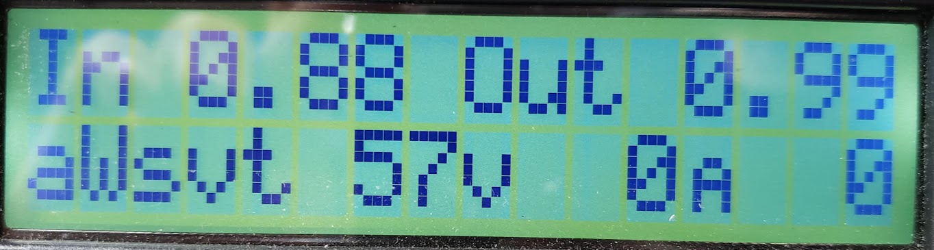
The above throttle diagnostic screen shows a standard grip-shift manual throttle, using a Hall Effect sensing mechanism, connected to the CA's throttle input connector. The "In" 0.88 volt signal shows the throttle in its resting position. The "Out" voltage of 0.99 reflects the minimum positive output voltage as set in the CA. Both these voltages lie within the standard throttle 'neutral' zone, meaning there is no acceleration or deceleration (regen) request being sent to the motor controller. If the voltage were to be pulled lower the controller would invoke regen if enabled. If it went higher (above 1.09, typically), the motor would start spinning.
The Throttle Setup process involves the selection of a MODE which defines the throttle's behavior. While there are at least 7 different modes, only two are relevant for us here. Refer to the list of CA3 Setup Settings at Grin under "Throttle In" and "Throttle Out" to see the full list of possible modes for the current version of the firmware.
We typically select the Pass-Thru mode once we've confirmed that the manual throttle is functional. This allows the rider to use the throttle to override whatever other assistance schemes (typically PAS and/or Torque) are in play. Note that some firmware versions, including skateboard, do not support the use of ANY manual throttle, in which case the Pass-Thru is also the correct mode to select.

In the CA display above we see that the CA is taking control of the throttle output signal being sent to the controller without the rider having touched the manual throttle. The 3.54 "Out" voltage pretty much means the motor is spinning full speed (note the bike's speed of 24MPH!) while the 0.88 volts remains unchaged. We can also conclude that the bike is 'coasting', since the motor is drawing "0" amps ("0A") -- an unlikely reading if the bike were under power. The display was photographed after the throttle "Out" signal had been wide open (WOT), causing the bike to accelerate to full speed, and the CA is now slowly 'ramping down' the throttle towards the neutral zone. In this example, the throttle had gone to WOT because of a combination of PAS and torque inputs, simulating a rider pulling the powerlever on the erowbike1.
Had the positive throttle voltage signal been quickly 'cut' down to BELOW the neutral zone and the bike had been on the road, the bike's mass/inertia would cause the 0A display go to some negative number, meaning that the controller had switched into regen mode and the displayed 'negative' current was going back into the battery. The resulting effect is what we call 'electric braking'.
Also of note is the "aWsvt" on the display. Each letter reprents a certain parameter that the CA is capable of controlling. If a letter is displayed as a capital letter, it means that the CA is actually exerting control over that parameter. In turn, the letters are shorthand for: amps, watts, speed, volts, temperature. In our example above, the CA is exercising active control of the POWER (using "watts" as the unit of measure) being used on the erowbike1. This leads us to the next setting that affects the behavior of the e-assist.
The Cycle Analyst sends the Throttle OUT signal (ThO) to the motor controller via the CA-DP connector. It can be set up as either a variable voltage signal for ebike controllers or as a digital 1-2mS pulse for RC controllers. The min to max output range should be adjusted to correspond to the throttle input range of the controller to ensure the controller is driven to max at full operator throttle and is completely OFF when the operator throttle is closed. The extensive ramping options can further help achieve smooth power engagement and remove the aggressive edge from powerful motor systems.
Selects between a steady analog voltage output on the CA Throttle Output line or a 1-2ms RC servo style pulse output. Almost all ebike and EV controllers operate off a voltage throttle signal, while the R/C pulse mode enables the CA to control compact ESCs from the hobby industry.
This is the voltage or pulse width sent to the controller for ZERO rider throttle. It should be about 0.2V below the actual voltage where the motor controller starts to respond. The default value of 1.0V is fine for most setups, but if the controller does not start turning the motor until 1.4 or 1.5V from the CA, then the Min Out setting could be increased to ~1.2-1.3V for a faster throttle response with less deadband.
This is the voltage or pulse width sent to the controller for FULL rider throttle. Most ebike controllers will achieve full output between 3.5 to 3.9V on the throttle, and the CA3's Max Out should be at least 0.1V higher than this to achieve full power.
NOTE: Many controllers have a throttle overvoltage fault similar to ThrI->FaultThrsh. The CA3's Max Out must be lower than this controller fault or the controller will shut off at full throttle.
Determines the maximum rate at which the throttle output can ramp downwards. For safety reasons you would generally leave this at a high value so that the system can shut off promptly, but there can be times where a slower disengagement of motor power is preferred. Values of 4 to 8 V/sec are recommended. Ebrakes cut power immediately and are unaffected by this setting.
Determines the maximum rate at which the throttle output can ramp upwards once current greater than FastThrsh is detected. This setting is popular for smoothing out the harsh kick on powerful systems. A lower value in V/sec will result in a longer time for the throttle to ramp up and results in a more gentle application of power. Values of 0.5 to 3 V/sec are recommended.
Determines the maximum rate at which the throttle output can ramp upwards when engaging in PAS mode. This can be used to achieve a smooth PAS power application while still allowing for a fast response with the throttle. Operation is otherwise as with UpRate.
Determines the maximum rate at which the throttle output can ramp upwards when controller current is less than FastThrsh. When current reaches FastThrsh, the rate becomes governed by UpRate or PASRate. This dual rate approach allows the Throttle output to quickly reach a level that starts having a measurable effect on the motor before then dropping to the normal Up or PAS rate limit. This eliminates time lag for a ramped throttle output to catch up with the bike when you apply the throttle and are already moving. Values of 3-8 V/sec are recommended for controllers that have an immediate response. For controllers with built-in ramping (such as eZee), or sensorless controllers that have a startup routine delay, a lower FastRate rate may be required to prevent overshoot.
Determines the threshold controller current at which the CA's output ramp switches from FastRate to UpRate or PASRate. This setting should be quite low for direct drive hub motors, such as 1-2A. However, for gear motors or mid-drives, the setting should be a bit higher than the no-load current required to accelerate the motor from stopped, typically 2 to 4 Amps. A value of 0A disables FastRate so only UpRate or PASRate is applied.
These settings configure power and current limits for the ebike. The Cycle Analyst cannot increase the natural limit of the system, so setting the CA current limit to 40A will have no effect if you have a 20A motor controller. However, you could use it to limit current to only 15A to avoid over-taxing a small battery that is not rated to deliver full 20A discharges. Both the Amp and Watt limits have associated feedback gains that may need to be tweaked for a quick response without oscillation or surging.
Sets the CA current limit in Amps, commonly used to reduce stress on the battery pack or limit the available system power. This value may be further scaled down by one or more of the throttle, the Analog/Digital Aux inputs, or temperature limits. This setting can be left at the default high value if no CA current limiting is desired, but if either thermal rollback or aux / throttle amp adjustments are active, then MaxCurrent should be set equal to the controller's battery current limit.
Sets the CA power limit in watts. It has very similar effect as a current limit, except that the resulting power does does not change with variations in battery voltage. This is typically set to no more than the battery voltage times the smaller of the controller current limit or the continuous current rating of the battery. This setting determines the 100% power setting for Power Throttle or Aux Input power scaling. If neither of those features are used, this setting can be left at the maximum value.
Feedback gain for the current control loop. This affects the current limiting response and can have a noticeable effect on throttle behavior when operating in Current Throttle mode. If this setting needs adjustment, increase it until current limiting begins to be rough or oscillating and then reduce the setting by about 30%.
Feedback gain for the power control loop. This affects the CA's response in any power limit mode, which includes Power Throttle and most of the PAS modes, even if the normal Max Power limit is not in play. If this setting is too high, the system may be prone to surging and oscillation while maintaining constant power, while too low of a value can result in a sluggish response. Typical values for well behaved WGain are 8-25.
Re: Cycle Analyst V3 preview and first beta release by justin_le » Oct 03 2018
Assuming that you have a controller that can do regen in the 0.0-0.8V throttle region (like a Grinfineon or Phaserunner), then there are actually 2 ways of activating regen without an ebrake input to the CA3.
#1 Set your Min Throttle Output to a value in the regen region: This is more or less like a setup that has engine braking, once you let go of the gas the vehicle slows down faster than if it was just coasting. We've seen people with Phaserunner's set the min throttle output voltage to like 0.6 volts to achieve this effect. It's more popular for scooters than for bikes since most cyclist want to be able to relax the throttle and still coast, but for bikes that have a PAS sensor it works OK since then you only have the regen brake come into play when you stop pedaling too.
HJ: This probably wouldn't be desirable on the eRowBike1 because if a rider was using only the throttle, they'd expect to coast when releasing the throttle. If they weren't using the throttle at all, the bike would be constantly in braking mode due to the sub-0.8V "ThrO->Min Out" setting on the CA. If PAS were enabled and the rider stops rowing, they'd probably still prefer to coast freely.
#2 Enable Regen Speed Limiting: This way whenever you are exceeding the speed limit the bike will do proportional regen to slow you down. If you combine that with either the aux potentiometer or digi-aux control set to vary your speed limit, then you can easily slow down right to a stop via regen without a separate button input. I've actually grown pretty fond of this method and have used it as the primary means of using regen in certain setups (like a rowbike) where it's less awkward than using the brakes and a throttle.
HJ: This would be implemented on the eRowBike1 by using the digi-aux (up-down) buttons to decrement the speed limit setting to slow down. The problem is that you'd have to increment the speed limit again to resume normal speed. I think I'd prefer having a momentary pushbutton to activate the ebrake circuit and slow down to the default ebrake setting and use the throttle (maybe a thumb throttle vs a grip, if that is ergonomically easier) to slow down faster/further.
The number 3 option which has been prototyped but not yet incorporated into the main CA3 firmware is regen that [is] activated by backwards pedaling when you have a PAS sensor attached. We hope to have this featured incorporated into a later release build since it's nice to have options that don't require extra brake sensors on the bike.
HJ: The problem with this on the erowbike1 is that each return of the powerlever (being half of each complete stroke!) will be interpreted by the CA and our custom PAS sensor as "pedaling backwards", resulting in undesired braking on each power stroke.