Legacy use only: company bankrupt and systems no longer officially supported.
| Directory | |
|---|---|
| BionX Hardware | Motor, Battery, Wiring/Connectors |
| Notes | |
| Bionx CanBus Battery Rebuild Options? | Endless-Sphere thread, 2015 to current |
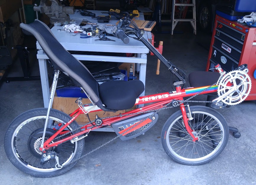
After concluding that the stock BionX system would not meet our primary needs of providing e-assist for our eRowbike project, we installed it on a stock Rans Rocket recumbent to give it a second life. We used this bike because we already had two on hand, and it was designed to use a 20 inch (DIN 409) rear wheel. The conversion was straight-forward, requiring only a battery mount and adjusting the motor's orientation to the recumbent's chainline. This bike worked OK for several thousand miles, until the "blown" battery connector issue detailed below . The recumbent's range with the 48V battery easily went to 60 miles, as long as I did some of the pedaling. We installed and frequently used the BionX manual throttle in addition to the built-in auto-assist.
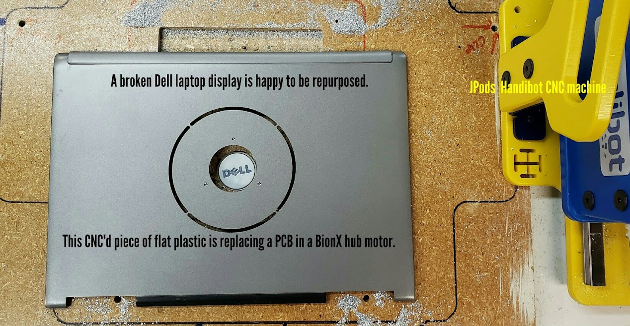
Ultimately we decided that the Rans was not a good platform for a rear hub motor due to stability issues. Better weight distribution and an effective suspension system might have made for a different conclusion. The quality of the motor and the lipo cells used in the battery were good, and the system was very reliable other than the *connector* issues. Unfortunately, this has been the bane of many ebikes, and is a frequent source of failure. As of early 2021, the BionX motor is still in pieces on the workbench, waiting to be converted to a 'conventional' direct-drive rear hub motor, albeit one with a built-in torque sensor. The plan is to use a custom printed circuit board (PCB)inside the motor to amplify the original BionX strain gage output for use in an e-assist system. Good intentions...
The older BionX hardware, typically through 36V battery packs, uses the I2C protocol on the "comm" (data/signal) cabling, while the newer 48V systems use the Canbus protocol (change to canBUS was 05/2009??). The green and white wires are SDA (data) and SCL (clock) for I2C, and High and Low for CanBus. The BionX hub motors all have proprietary controllers built into the motor housings, and include firmware (read/write registers) that read the motor's internal strain gage to deliver proportional power -- depending on the assist level settings in the console, which also has firmware and a microprocessor in it. While the battery is "smart" and also includes a PCB with firmware, it apparently isn't crucial to the system's basic functioning, other than providing regulated 5VDC on the red and black comm wires to run the PCBs, and, of course, report its own state-of-charge ("SOC") status to the console.
There is a strain gage torque sensor built into the rear hub which the controller (also built into the hub motor) reads to determine the amount of proportional assist provided to the rider. The hub motor *must* be specially aligned within a required 5 degree range to the notch in the axle facing directly downwards. The reason for this is that the torque is measured by the pull of the bicycle chain on the top of whichever sprocket of the rear cassette is currently the gear being used. The harder the chain is being pulled on the sprocket, the greater the amount of assist provided. This means the motor alignment will be significantly different for a recumbent bike with the pedals in front of the rider than it would be for a standard 'upright' bike where the pedals are below the rider. See more details about this below.
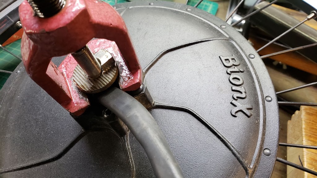
In the photo above we see a 1960's era VW steering rod puller being used to loosen the special BionX washer which is used to orient the axle in the correct angular relationship to the top of the rear freewheel cassette. The rectangular "bump" fits into the rear dropout slot, and when the axle nuts are tightened, the special washer is locked into place via a taper fit on the axle. This operation needs to be performed every time the hub motor is installed into a different bike frame where the geometry angles are different.
Alan on ES says:
"First, make sure the axle notch is perpendicular to chain center. On most bikes the pedal rotation axis and the rear wheel rotation axis are at the same height off the ground, so the chain center would be perfectly horizontal. Therefore, the axle notch should be vertical (straight down). I'm not sure how your tricycle is set up, but if the chain is not horizontal, then the notch should be not be vertical." [See more of Alan's comments in the software sections below.]
I think Alan would define "chain center" here as a straight line between the bike's bottom bracket (pedal shaft) and the rear wheel (motor) axle. The BionX motor's "axle notch" would vector away from that line at a 90 degree angle, facing downward towards the ground. You can test the torque assist by clamping the rear wheel against rotation and then applying a pulling force on the chain. If the controller is issuing a command to the motor to provide assist, it will add small bars in the display on the console (the inverse of regen seen in the bar display on the left side).
Alan, on ES:
'The BionX, as with nearly all ebike systems have a top "target" motor speed that is a function of voltage times the motor constant, Kv. [The target speed (V * Kv) is a no-load speed] That top speed is motor RPM, not MPH. Once you are above the voltage * Kv motor speed, there will be no assistance from the motor. The greater the speed difference between the motor RPM and the target speed (V*Kv), the greater the current. When the motor is turning slower than.the top/target speed, then the battery will discharge, and when the motor is faster than its target speed, the battery will be charged.'
"BionX - How to fix the motor" thread: Post by justin_le Nov 04 2018
Rony wrote: Nov 04 2018 10:21am Hello, thanks for reply. Any suggestions where I can buy a new one (or used one) ? Maybe someone here has some boards for sell ?
Justin: Presumably there is someone out there who has a pile of controller PCB's from the BionX liquidation auction this past summer, and with BionX no longer in business there will surely be lots of used / broken kits being sold or discarded which you could scavenge the motor controller board. That's what you should do if you wanted to keep this as a BionX bike (with the same console and battery etc)
But now that you've got it open like this I would seriously consider liberating the motor from the BionX platform and instead bring out the 3 phase wires and 5 hall wires to an external cable. Then you have the freedom to use literally any 3 phase BLDC ebike motor controller, and you'll also be able to use any model of battery pack too. It'll be much more versatile as an ebike down the road. We've done this with a BionX PL350 that was donated to our shop which also had a broken internal controller. See the phases connected to the yellow, green, and blue motor cable.
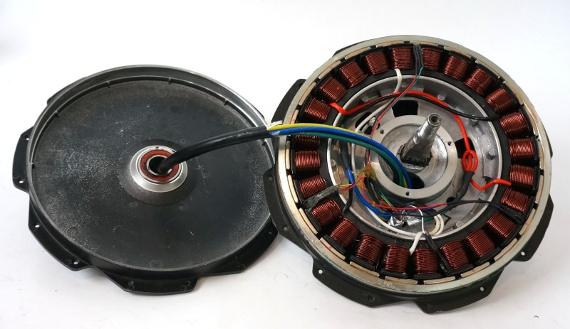
It's now a fun and peppy setup running at 1500 watts peak and with Statorade to enable much higher power levels than the original system without the overheating risks.
We'll be removing the factory-original controller PCB in the motor and replacing it with a non-conductive plate that will help protect the remaining wiring. Another handy use of the HandiBot CNC router.
As of mid-2021, this BionX project is still waiting in the bench queue.
There is a thermistor/temperature sensor inserted between the cells of the pack, and if the pack exceeds ~140F the battery is completly disconnected electrically from charging and discharging. Using the pack without the onboard BMS would eliminate this protection. The BionX system does regen, with the display showing you how much by way of a sliding bar graph. Above a certain speed, or it the battery is too full, the regen goes to a resistive load (dump) instead of the battery. The amount of regen I've experienced with BionX is much more conservative than what can be achieved with Grin technology.
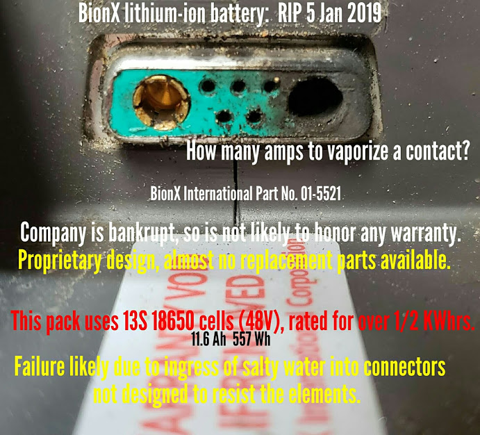
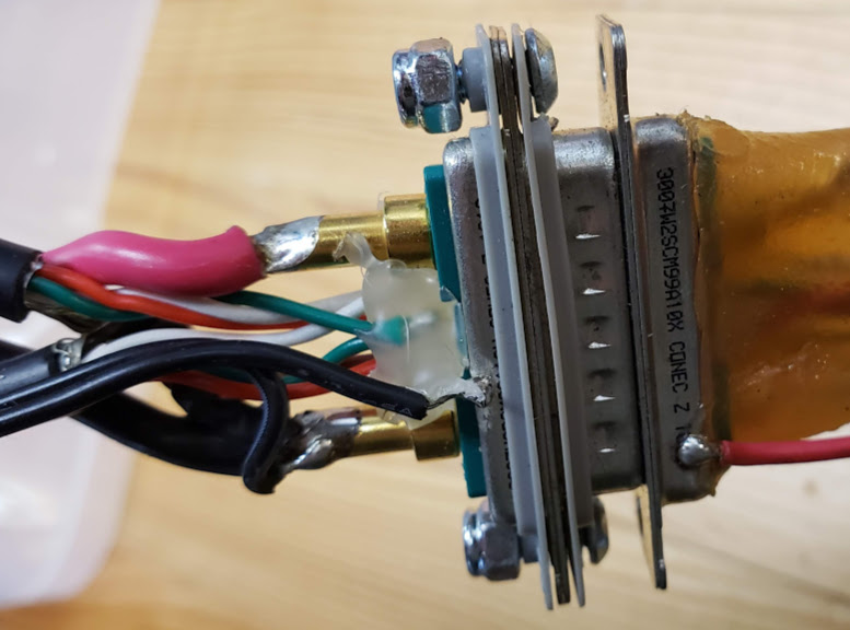
The photo below shows the rear connector of the BionX 48V downtube mount battery connector. Note the blackened positive terminal on the right side, which *vaporized* the barrel material on making the connection to the system. The male positive pin on the battery mount also sustained severe arcing damage. The cause of this extreme short was at first suspected to be caused by salty water/ice/slush ingress at the connector, since it happened during such weather conditions. The battery's internal 30A automotive type inline fuse remained intact, suggesting it took less than 30 amps to make the connector disintegrate and result in an open circuit, or the short circuit current never reached that fuse. There is no visible damage inside the battery case, and except for some minor corrosion where the five control wires are soldered into the BMS board, everything looked good. At the time the battery was mounted to its rail and resulted in this damage, it was fully charged via the factory charger and the charge port green LED ring lit when touched. The display was still working fine after the positive terminals vaporized, although (obviously?) no power was delivered to the motor.
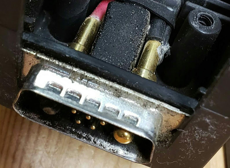
This happened in mid-winter in Minnesota, with exposure to moisture and salt, which is why environmental issues were suspected as the cause. The text in the photo saying that's the "likely" cause was pure guesswork, and it turned out to be wrong. I did keep connectors clean and protected with dielectric grease. All wiring except that going directly to the motor was inspected and there were no open or short circuits. The possibility of a fault condition (dead short?) in the motor itself or the power wires going to it were a possibility. I looked at this when the weather got above zero again and the motor power/comm cables all checked out OK. Resistance measurement on the motor's phase power wires reflects reasonable resistance values, changing during readings, suggesting the presence of capacitors in the circuit being measured. The following shows the "male" half of the connector, which also sustained severe damage to the positive power pin (in the shadow on the left side of the photo).
After the damage was done, the battery still seemed to be a happy camper, with the green LED ring and small beep behaving as if nothing had happened. So the title above about a "blown" battery is somewhat misleading. Battery pack voltage remained at a healthy 52.* volts and shows no tendency towards self-discharging. The G2 console display did show an "Error 63" however, along with the 'wrench' fault icon.
A year later, in January of 2020, the battery still appeared healthy and took a normal charge. I will attempt to use it as a 'generic' 48V battery with a Grin motor and controller.
After replacing the "blown" D-sub connector with a good one from an older 36V pack, I stuffed everything back in, making sure the BMS card was securely slotted into its dedicated recesses in the bottom and top portions of the case. Now the green LED ring around the charge port no longer lit up -- in fact, the battery appeared to entirely dead. I remembered something about "waking up" a BionX battery if the voltage had gotten too low or if it had gone into "Deep Sleep" mode due to non-use, so I looked into that. Googling "how to wake up a bionx 48 volt battery" returned some hits that said to do the following:
Connect the charger. The battery can be mounted on the bicycle or removed. The touch port LED will blink green and beep 4 times as the battery turns back on. It will then start charging.
Since I knew this battery was fully charged and therefore not suffering from low voltage, I hoped it was in Deep Sleep mode instead of being Dead. I knew the cells were good, so if the battery is now dead it's due to a bad BMS or bad connections.
The following explains what causes the battery to enter Deep Sleep mode:
A fully charged battery will automatically enter Deep Sleep after 2 months, while a partially discharged battery will enter it in increasingly faster time frames.
References:
Online site with BionX info (link good in 2020):
https://newwheel.net/questions/pages/viewpage.action?pageId=10846261
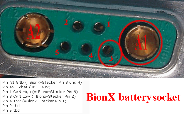
This post on ES [https://endless-sphere.com/forums/viewtopic.php?t=75347] shows the following photo with schematic notes. The German word "Stecker" means plug/connector, so the notes show the pin functional correspondence between the physical "battery" connector (shown) and the "BionX" connector (not in photo).
Since the system is normally turned on by pushing a single Power On/Off button on the (G2) console, it should be doable via just manipulating the signal/data "comm" wires:
Result? After first *waking* the battery by plugging it into the charger, the green touchport LED lights up again, it beeps correctly (3 times), and the console (G2) will turn the system ON/Off again. It does display a "wrench" fault icon and error code 60, however, with the motor plugged into the system.
For using the BionX battery with other systems as a generic 48V battery, I will try to keep the G2 console connected to the battery as an ON/OFF control and see how that works. If I can confirm that simply keeping the "wake" line (pin #3 on battery connector) shorted to GROUND is workable, I can replace the console with a simple SPST switch.
The Canbus battery puts 12VDC on the comm/signal cable to the motor, in case that's useful for something. Probably enough to run small lights.
After all the dust settled and magic smoke cleared away, I'm left with the following conclusion. The BionX engineers were likely faced with the challenge of having to add one more function -- a 6VDC power source for the lights? -- to the existing BionX wiring harness. Not having any more available wires, they apparently made the unfortunate choice of using the metal D-shell battery connector to do this. You can confirm this via a multimeter test and seeing a hand-soldered wire (either Red or Black!) soldered to the outside of the metal D shell. (See photo below.) So while every other application in the universe makes the shell of a D style connector a safety ground, the BionX folks made it HOT! What I think happened is that when I *removed* the battery from its slide-on/off mounting plate, I briefly touched (brushed) the battery's HOT (12VDC) metal D shell to the large brass Negative (ground) pin on the mounting plate. This effectively shorted the 12VDC supply on the controller board inside the battery to Ground. Apparently this supply is NOT FUSED adequately, allowing sufficient current to flow to effectively vaporize the Ground (A1) pin in the D connector (see photos above). The big metal D shell had sufficient conducting mass to avoid being significantly affected. The now destroyed 12VDC supply section in the battery is likely to be causing the error (60, 63) display on the G2 console (not yet confirmed). If I don't need the 12VDC function, maybe I can just ignore this error and use up the battery elsewhere.
Jan 2020: I'm now trying to use the battery for a generic ebike installation. Using the factory original G2 console's power-on switch does in fact turn on the system. However, the BionX G2 display, after booting up, shows a "POWR PROT" message at the bottom of the screen, and the two power wires going to the motor are dead, even though the battery is "alive". According to the original BionX documentation,
[http://ridebionx.com/bbi/smart/DE_EN/RL32%20-%20Repair%20instructions%20for%20drive%20system%20diagnosis.pdf]
this means the following:
Fault code "powr prot":
There is a fault in the 12V or 48V line, preventing the drive system from functioning. Check the communication and power
cables for damage (chafe marks, broken cables, contact between the wires and the frame etc.). Replace the affected
components if necessary.
Chrisbeck schrieb:
. "Müsste sich das System ohne Motor einschalten lassen, evtl. mit dem Hinweis, dass der Motor fehlt?"
Reply by user "cephalotus":
Lässt sich ohne Motor einschalten. Im G2 Display erscheint dann als Fehler: "POWR PROT"
...
Für mich bedeutet "ohne Motor", dass beide Kabel nicht verbunden sind. In diesem Fall verhalten sich meine Systeme wie oben beschrieben...
Per the reply to the above post, even if the motor is NOT CONNECTED to the system (G2 display/controller plus battery/BMS), the power button on the G2 will TURN ON the system display, but the POWR PROT message will be displayed and no power will come from the battery. This post is consistent with what I've experienced so far. It would appear that the BionX battery can't be used unless the (BionX only?) motor is connected. Unless a method can be used to fool the system into thinking that the motor is attached -- if we knew what signal (resistance, inductance, active signal?) is provided by the BionX motor.
OTOH, one person reported that POWR PROT message appeared after the SIGNAL cable connector to the motor became loose, while the power cable to the motor was still secure. This suggests that a break in one of the signal lines is enough to trigger this fault.
(COMMUNICATION A , ... POWER B).
Und Stecker A hat sich gelockert, also der, der für die Kommunikation zuständig ist.
https://docplayer.org/52826778-Bionx-codes-error-kompendium-version-0-08.html
POWR PROT:
POWER PROT displayed on G2 console Anzeige POWER PROT auf G2 Console, keine Fehlercodeanzeige Motor (zeitweise) nicht mit Strom versorgt oder Kommunikationsfehler Stromverbindungstecker am Motor prüfen Motor not receiving enough voltage from battery. Can indicate a communication error between console motor. Check all connections and battery bracket. Double check the console and dock, if it's too tight or too loose it can cause this problem. Check the wires running to the motor - they may be damaged or frayed. If they are, send to BionX for repair or replace it. Lässt sich nicht normal einschalten (sehr langer Druck auf + notwendig) Kein Ausschalten möglich. Keine Unterstützung. Akkuanzeige zeigt teils leer an obwohl der Akku voll ist Ruckeln des Motors, zeitweise. Display wird nicht übers BIP erkannt, sonst keine Fehlermeldung. Steckverbindungen sind trocken, Problem trat plötzlich auf Resolved my BionX "POWR PROT" error issue last week; it was a loose power cable. Hallo, den Fehler hatte schon mal ein anderer User. Steckverbindungen und Kabel überprüfen. Am besten einzeln auseinander und wieder zusammenstecken. Gegebenenfalls mit Kontaktspray nachhelfen.
Fault code 60:
A wrench appears in the display and the front/rear lights are inoperative. Check the light cables and their connections for
damage (chafe marks, broken cables, contact between the wires and the frame etc.). Replace the affected components if
necessary.
Fault code 66:
A wrench appears in the display, the battery emits an acoustic signal and the drive support system is inoperative. Make sure
that the rear wheel turns freely and switch the system off and on again. If the acoustic signal stops but the drive support system
remains inoperative, replace the motor. If the battery continues to emit the acoustic signal immediately after switching on,
repeat the process with a different battery. If the acoustic signal is emitted again with the second battery, the motor must be
replaced.
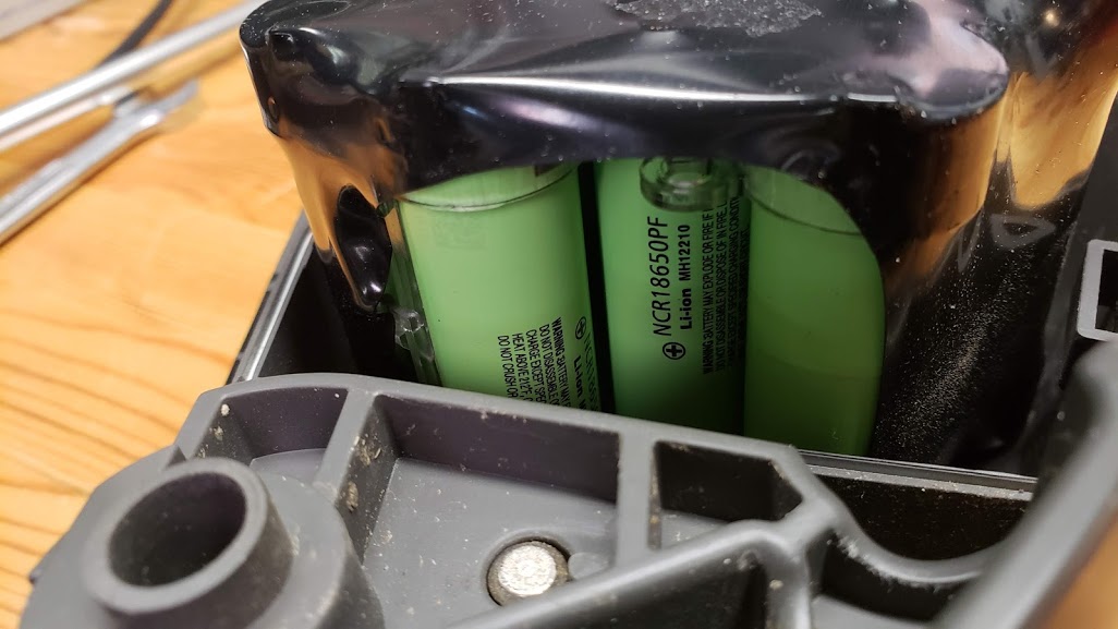
This peek into pack shows the cells used.
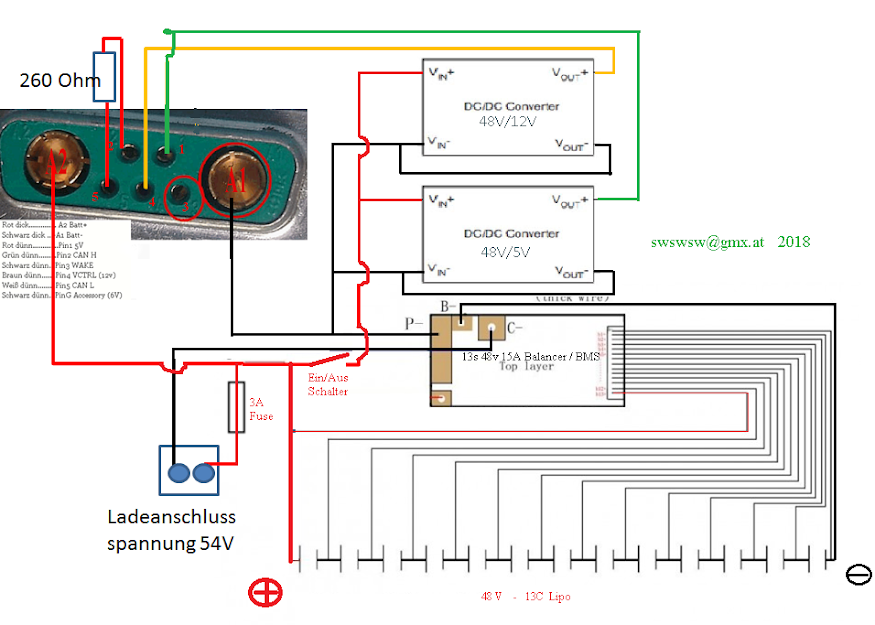
This schematic, courtesy of a German website, shows an overview of how the BionX battery might be connected when the proprietary BionX system is no longer working correctly. Note the 12VDC and 5VDC DC-to-DC converters used to supply these needed voltages to 'fool' the system into working with the stock display and motor controller. The word "Ladeanschluss" means "charge port".
The following picture shows both the male and female D-sub connectors used to connect both the 36V and 48V batteries we have encountered. This set was 'harvested' from a 36V battery found orphaned at a LBS here in the Twin Cities. Both the cells and BMS were alive, but age and capacity of the pack are unknown. In addition to the red/black main power wires and the five smaller control/data/signal wires, the connector shows two wires used for the 6V lights/accessories circuit. It *appears* that the positive of the 6V circuit (6VDC+) is soldered (passed through) to the D-sub connector shell, while the 6VDC- is connected to the negative/ground of the main (traction) battery. The connector's shell is NOT connected to any grounds. We used the battery side (female) connector to repair the 48V battery shown in the section above.
This German language PDF shows the functions for each of the wires in the BionX connectors for a "TinyCAN D-sub 9 pin connector going to the stock Hirose HR30-6 plug/sockets used to carry the control signals. It does NOT show the pin definitions for the *battery* D-sub connectors.
There are two connectors on the console/display bracket.
1. A 6 pin Hirose HR30 "Canbus communication" connector that is keyed and spring locked. It connects to the mating connector coming from the battery. [Hirose connector HR30-6P-6S(71); Mouser part number 798-HR30-6P-6S71]
2. A standard coax 5/2.1mm DC power "barrel" connector, which connects to the +/- and throttle buttons (G2 Throttle) typically mounted to the handlebars.
... this is from memory, there are two settings that will get your assistance at the level you want (after making sure the notch is set right!). I believe they are 0007 and 0008. The first determines, if I recall correctly, how readily the power will be applied. If that is set too sensitive, then the bike may take off before your feet are fully on the pedals! You don't want it to engage under a few MPH for safety. I don't see from your post that this is a problem, but I think the factory default is a bit too high, and you may find this will help. [Actually this is the "Minimum Speed" setting below.]
The 0008 setting is a double setting, an A and a B value, which determine how sensitive the torque sensor is, and either your notch is too far off, or this setting is way too low for you. If this is set too high, your feet will get less workout on the pedal than your thumb will on the throttle! The B setting (I think) determines how much power is applied for a given torque input. This can be made so high that a level 1 assist will give you more power than the default value does for level 4 [Alan is talking about the console/display setting level here; 300% assist at level 4].
I found that default settings for level 4 is virtually useless, unless I did not want any exercise; might as well use the throttle. Level 3 is very aggressive, and level 2 is more than I typically want. However, I found level 1 was barely more assist than compensating for the weight of the system itself. I wanted to do most of my riding between 1 and 2, so I bumped up the 0007 and 0008 settings to get exactly what I wanted, and now I ride about 90% of the time at level 1. Sometimes I go to 2 or 3 near the end of my ride just to cool down. I rarely use the throttle.
I'm guessing the BionX system is optimized for a 40-60 RPM cadence.
Note that by setting all the amplification factors to their maximum values, it's possible to have the motor kick in even without applying the throttle or pulling on the powerlever. These values should be programmed while the Rowbike is on a test stand.
Thank you Scott for your time today.
Please understand that we never did a Rowbike, and we will need you to do some testing.
There is different setting that I would like you to play with at first.
On the right side in BBI will find system profile, please select Custom and then play with those 2 setting.
1) Overall gauge multiplier (0007): try to increase to 2
2) Gain A (0008a): try to increase to 2
That should really increase the power even with low arm power. Please be aware that we multiply the signal from the torque sensor. By having it to the maximum for 0007 and 0008a, the signal from every other aspect than pedal assist will also by amplify. It could result with auto assistance, but the only way to know is by testing. If you feel that power appears even without pedaling, please start reducing the 0007 and 0008a.
Once you have selected the best fitting, I would like to adjust the filter that will adapt the responsiveness of the system. As discuss over the phone having a Rowbike instead of regular pedal reduce from 60-80 rpm to probably more around 30 RPM.
Still into the same menu, you could ajusst the Gauge filter (1234)
4 = system start quickly but stop quickly
1 = system start very slowly but stop more slowly. What help to compensate for the slow RPM.
I'm not sure what would be the magical number for that bike, I would expect level 2, but by testing it, you will find the best configuration.
Last setting is the min speed. You will find that setting bellow the console into BBI. For that type of bicycle I would reduce from 3km/h to 0.5km/h. Once again that is only suggestion, and please validate it before making it try to an end users.
Scott and HJ please call me for any questions.
Regards, Alexandre Coulombe
Everything you ever wanted to know about BionX... by Calf that is dead » May 05 2007 ======================================= ScotterMonkey Joined: Aug 08 2008 5:16pm Re: Everything you ever wanted to know about BionX... by ScotterMonkey » Mar 01 2009 10:39am 0007 : Sensor sensitivity: Set to 3.0 or less if you get too much "on/off" 0008 : Extra assistance: Set "A" to 4.0, Set "B" to 3.0 (when it kicks in) 3773 : Max speed (assist), set to OFF (0) 3775 : Max speed (throttle) , set to OFF (0) 3776 : Speed motor will start, set to LOW (1) 2006 : Brake sensor, set to ON 1234 : Sensor speed signal , set to 3 1970 : Configuration backlight. Set to OFF 1976 : Motor direction. Set to 1 (forward) 2001 : Set to km/h 2002 : Generative braking, set to max (64) 2003 : Activate battery remain display (toggle) 2004 : Set the clock to current time 2005 : Set wheel size to 2075 2007 : Polarity throttle, set to 0 3771 : Set wheel size to 2075 3774 : PR ? set to ON 3779 : Time and Distance remaining display, activate if not active already. Menu code 5000 to reset console Menu code 3772 to set console to diagnostic mode Menu code 0041 to activate 12C. Unknown setting Press and hold Mode for 5 cycles of backlight toggles to reset battery. Will beep rapidly when reset. Hold Mode button 2 seconds for backlight Press Chrono and +A or -G to set display contrast Press Chrono to select display type. Hold Chrono 2 seconds to reset data Press and hold Mode and +A to arm alarm With 0007: 1.0 is too low and the controller often doesn't detect the cyclist pedaling. Set to 3.0 allows detection of cyclist earlier and more sensitivity to changes in cyclist torque output. Diag mode (menu 3772) allowed me to find that the "B" option on menu 0008 is best to be set to 1.0 rather than 25. This is the speed where extra assistance kicks in. If this is the case, it's probably better to have it kick in at a lower speed. The assist power (upper left digits in diagnostic mode) were higher with the 1.0 value and seemed to climb faster from a complete stop. #3779 adds 2 more modes to the normal "chrono" display which can be useful if you want to see how much longer and how much further you can go (estimate). Maxed out #2006. When I use the regen brake (with the mag switch) I want it to brake as much as possible. Axle bolts must be between 40 and 50 Newton Meters tight.
This unit is mounted on the handlebars and connects to the G2 main unit via the longer "red" wired DC coax jack, and the shorter "white" wired DC coax connector which goes to a NO (normally open) magnetic reed switch held in stick-on foam on the the brake lever - which also has a permanent magnet mounted to the brake lever.
I'm going to substitute a pushbutton switch mounted on top of the brake lever, just as on the eRowbike, which will act as the "electric brake" activator. According to the BionX documentation, shorting the two wires going to the brake sensor cuts off the power to the motor and activates the regen at the level programmed into the unit at the time. Pulling the manual left and left brake levers simply activates the mechanical rim brakes as on a normal RowBike.
This unit is mounted on the left side of the handlebars and connects to the G2 main unit via the shorter "white" wired DC coax connector. This is currently red pushbutton switch, replacing the NO (normally open) magnetic reed switch held in stick-on foam on the the brake lever. When the button is pushed, the motor power is cut off and the Rowbike goes into "regen" braking mode. The amount of braking you get depends on the system configuration, including the number of bars on the left side of the G2 console. ES member, in 2007 (referring to programming register): I also maxed out #2006. When I use the regen brake (with the mag switch) I want it to brake as much as possible.
Note: Regen current goes primarily into the battery, and if the battery is fully charged, the regen braking force will be reduced to whatever the system can dissipate via a resistive (dump) element -- which isn't very much. Also remember that regen generates as much heat in the system as does generating power, since electrons moving through the coils in the motor don't care which direction they're moving in. BionX systems monitor the motor's core temperature and start dialing back power assist whenever the motor temperature rises beyond a certain level. This is equally true for either pedal assist or throttle use.
We used the BionX system on the eRowBikeX to see if it would be a good way to provide e-assist to standard RowBikes. I wasn't.
Note that as of roughly 2018 all official BionX company units (primarily Canada and Germany) have ceased business and, apparently, disbanded their stock, IP, and other assets. There seems to be no entity (this is being written in early 2019; no change in early 2020) that is officially doing maintenance or selling replacement parts. Existing stock has a way of finding itself to market, but it's hit or miss at this point. We decided even before this BionX bankruptcy to not use its system for eRowBike development, largely because the firmware remained too proprietary for us to make the tuning adjustments we felt were necessary, even after the company provided some support in our efforts. This was also the case for deprecating the Shimano Steps mid-drive unit, at least for now. The basic issue is that the manufacturer obviously designs their product for use with "pedals" -- which we don't use on our RowBike projects. So far we've had the best results when combining 'open source' hardware components with Grin Technologies products, as we are continuing to do with the eRowBike1 development. Grin (Justin) is extremely adept, as well as willing, to make the best current technology accesible for our e-assist vehicle prototyping projects ("thinking outside the box").
Update 1 Aug 2023: I have not done any additional development work on this project in the last several years, and am not likely to unless a somewhat compelling set of circumstances should arise. If someone else were to be interested in continuing this project, I'd be amenable to helping with making the transition, including the transfer of relevant hardware that I would still have in my possession at the time (I'm now 75, so don't wait too long. I'm located in St Paul, MN, USA).