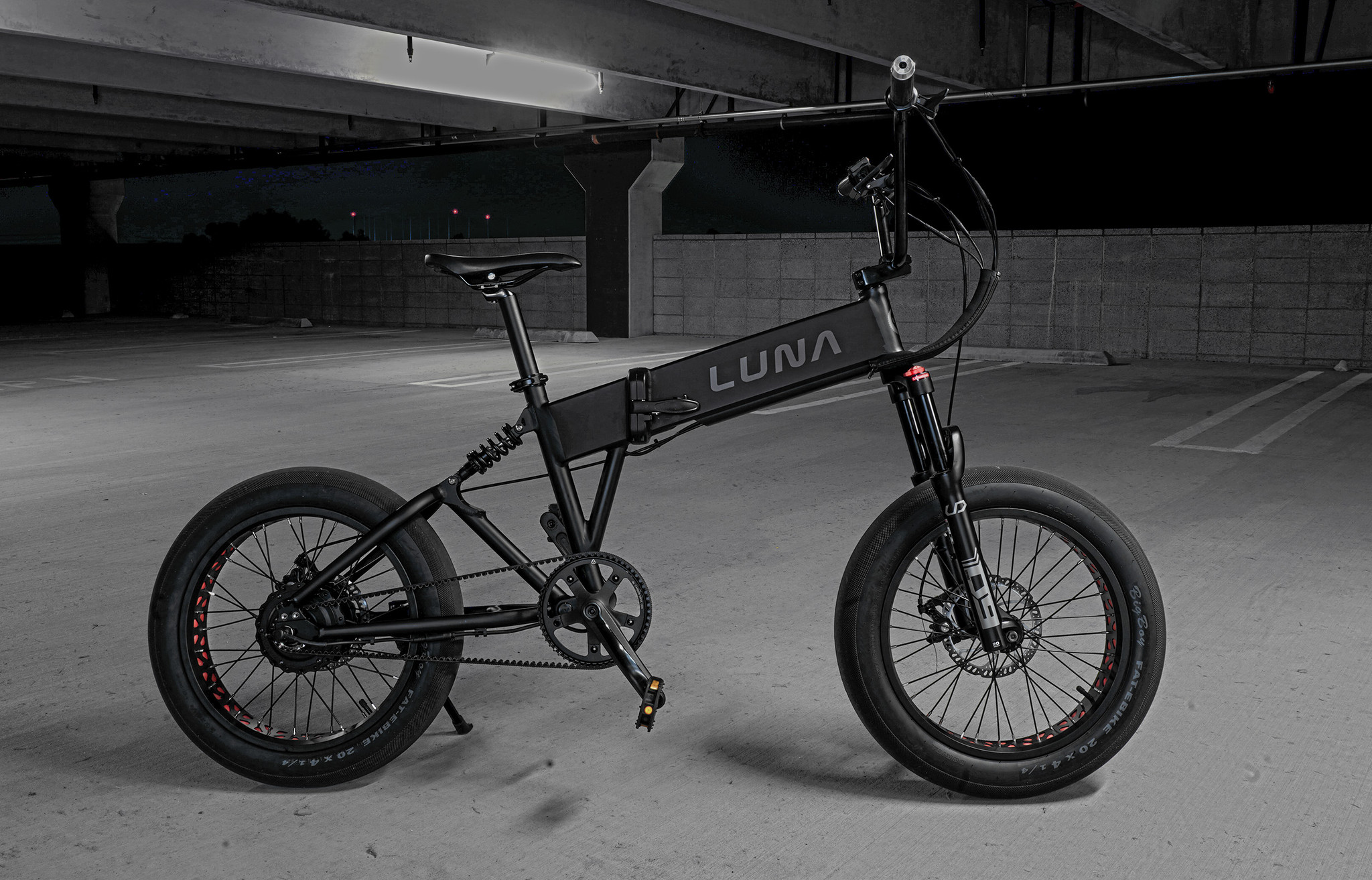
This is a photo of the Luna Eclipse ebike from the company's catalog page.
Per Luna, "it's a known Bafang G06 motor with a generic controller and a matched display." It is available in black or silver, but only in one size. It weighs 55 pounds.
Obviously the California-based Luna Cycle company does not manufacture the Luna Eclipse, but it does sell/service this model. Luna most likely selected this particular configuration from a Chinese manufacturer and imported it to the US for sale as the "Luna Eclipse" model shown on their website. Unfortunately this photo of a black bike against a dark background isn't the best choice for displaying its appearance.
Specs scraped from the lunacycle.com site Oct 1, 2023:
This basic frame also appears to be used with the Eahora X5 folding ebike with a 350 W Shengyi hub-drive motor motor. At least one difference between that model and the Luna Eclipse is that the Eahora uses a chain and derailleur vs. the Gates belt drive used on the Luna Eclipse. Also, the Eclipse comes with a rear suspension, which the X5 does not have. All of these frames appear to be all-aluminum construction. Below is a picture of the actual ebike we have (coming "soon").

This ebike uses the common Higo and Julet branded connectors in a standard configuration, so a good starting point is to review that. See Higo/Julet 2 to 6 pin "standard" connectors elsewhere on this site.
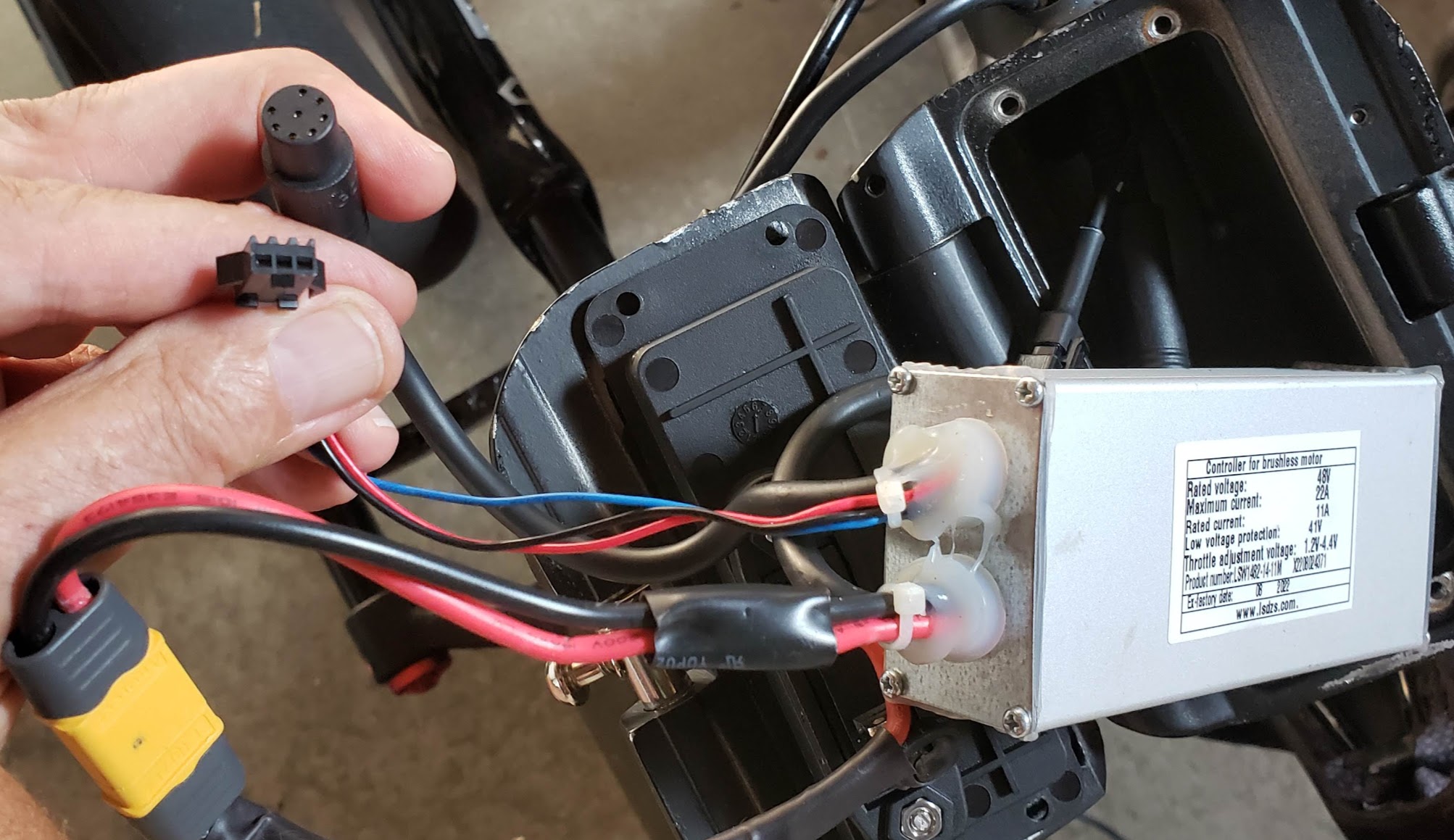
The cable connecting the controller to the Bafang rear hub motor is a standard 9 pin configuration, with three heavier wires for the phase current, three wires for the Hall signals, and three additional wires for the optional RPM data, temperature, and ...
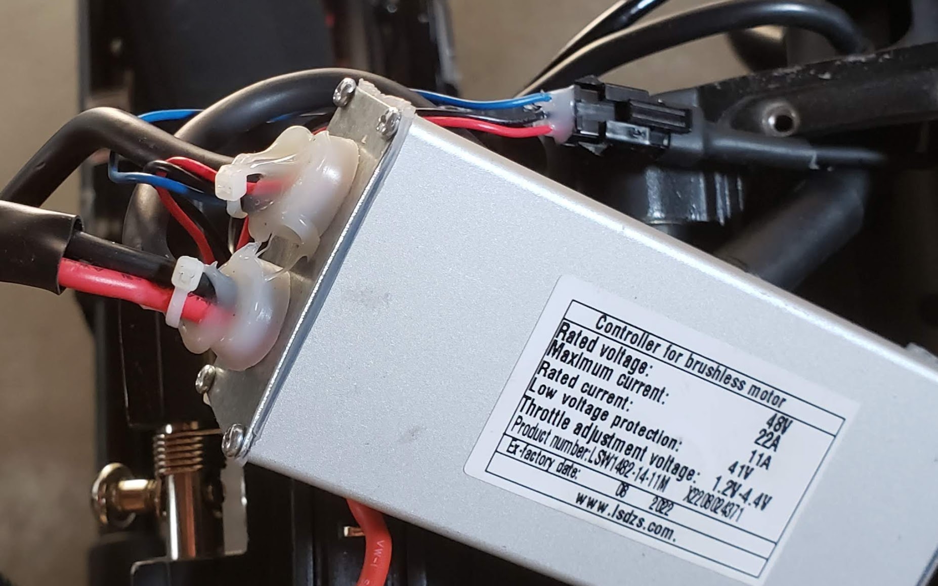
This is the 48V Lishui BLDC motor controller found in the ebike when acquired by us. It is made by LSDZS.com and has a rating of 11A (528 watts) continuous (22A max). This is very marginal for this ebike, but the controller appeared fine when the bike was acquired used in 2023. If the motor is putting out its rated 500* watts at 48 volts, it would be pulling 10.42 amps from the battery and through this controller. If the controller didn't somehow limit this current internally, it could easily overheat. Note the manufacturing date of August 2022. A 2023 search of the manfacturer's website did not return a result for this particular LSW1482-14-11M model. The 2023 version of Luna's website claims that the Luna Eclipse comes with a motor/controller combination capable of "1000 Watts of rear hub motor power (21amps continuous)".
* The same page also describes the same Bafang motor having a 750 watt rating. It's actually quite common to have wildly varying power ratings for the exact same motor. Controller power ratings are less likely to exhibit this behavior.
The Lishui model LD-LS83 (500 watts) appears to have similar specs as the LSW1482 model, but the website does not show plug and pin level data, which is necessary for debugging purposes.
During normal use, the controller and the corresponding wiring is stuffed into the ebike's frame cavity, seen here in the background. The wire bundles coming out the controller are split into the power section (battery and motor connections) and the display/control section (shown taken apart in the photo). Identifying each of the control wires in the Julet 8 pin female connector will be shown in later sections, below (eventually).
Testing the controller eventually ... confirm number of MOSFETs, etc. Probably a sine wave controller -- but could be FOC. Per ES, there exists open source software that allows (some?) Lishui controllers to have their firmware re-programmed. This would allow LVC, assist levels, speed limitation, etc. to be changed. Most controllers need power, ground, and one other pin "pulled high" to power up. This other pin is often called "Ignition" or "Power Lock" or similar. The mechanism used to pull this line high (to battery voltage) can be a mechanical switch or done through the display, or a combination of both.
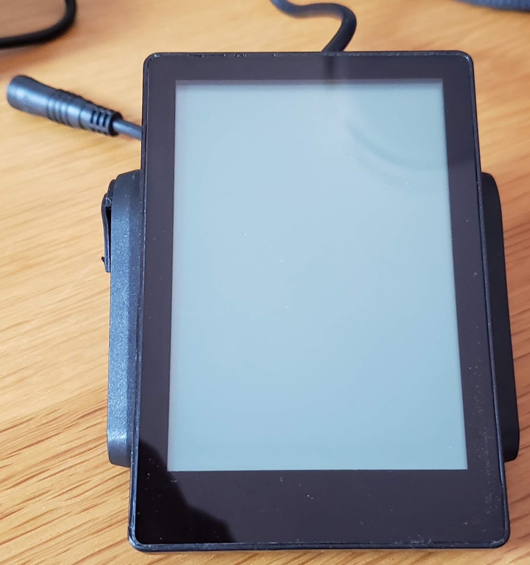
The biggest mystery at this point is the display used on the Luna Eclipse, which is not yet positively identified, but probably a Topology DS104. A failed display unit may account for the fact that this ebike will not power up in its current configuration. This display comes with a hardwired handlebar switch for all necessary control functions except the brake and throttle functions, which have their own devices on the handlebars. A display only needs power and ground to power up, so identifying these two pins should be the first effort. (Most controllers need power, ground, and one other pin "pulled high" to power up.)
Any time you encounter a display on an ebike or other LEV, it's handy to classify it into one of roughly three types/categories:
The display used on the Eclipse fits into the Type 2 classification. This photo of the front face of the display. Physically, this display bears a remarkable similarity to the "Brose DS103C Topology E Bike Display TFT 3,5" + Schalter BMZ DS103 Bloks Gen.2" found on the web. The 200 euro price tag for the high-end Brose brand doesn't seem to match this Eclipse display, but the DS103C is a color display while this is advertised as a monochrome. A touchscreen would also justify a higher price.
Showing the back of the OEM display unit with a "standard" Higo 5-pin/green female connector and cable, plus a separate cable directly connected to the handlebar control swith with the ON/OFF, "M" (menu) button, and the up/down rocker switches to change the assist level. The back of the display's plastic case has injection molding marks that include a "Topology" brand/logo, and a "DS104" model number.
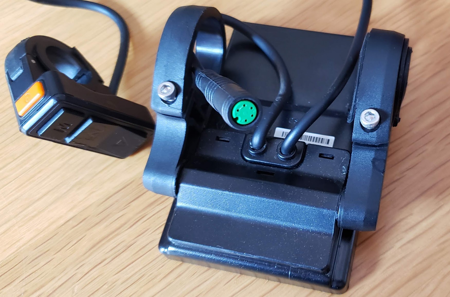
Two of these 5 pins/wires connecting the display to the controller will certainly be the positive and negative power connections. Since this display with its attached handlebar switches is used to power the bike on and off, one of the 5 pins/wires will likely be used to turn the main controller on and off. This leaves two wires to handle numerous other functions, and the only way that can happen is if there is an agreement between the controller and display on how to send this data back and forth. This is referred to as a shared communications protocol, and it must be the same for both devices. A mismatched display may light up when the power button is turned on, but it won't communicate correctly with the controller.
It should be remembered that in general it is the *controller* that dictates what the ebike motor actually does, and that the controller has the 'memory' of what settings are in effect at any given moment. Quoting Delphis1982 from pedelecforum.de: "Die Einstellungen im Controller überstimmen quasi jegliche Einstellung innerhalb des Displays." Roughly translated it means that the settings in the controller dictate whatever settings appear to be in the display. In many cases it's also possible to directly change settings in the controller via a separate software program running on a computing device attached to the controller via a compatible "programming cable."
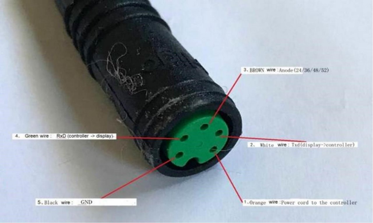
Or, they could also be following this pattern, where the display is connected to the controller via a transmit/receive communication bus [Kommunikationsmethode:UART(Standard)]. Note that in this case the colors of the five wires are substantially different. The brown "anode" pin in our case goes to the battery's 48V positive. The orange "power to the controller" pin/wire when shorted momentarily [~2 seconds] to the 48V positive line "turns on" the controller/ebike. Thus, for testing purposes, a momentary SPST switch between the brown and orange wires should turn the controller ON.
[photo courtesy of the German language site pedelecforum.de] See also this photo in this site's "Connectors" section. We should be able to identify the negative/ground pin, since it will have zero ohms to the battery negative terminal.
Higo/Julet connectors all have a small key on the male side and a corresponding notch on the female connector. All pins and wires identified by a number, starting with 1.
For our purposes here, these numbers will be assigned as follows. {or should we go with holding key at 12 o'clock ??}
Hold either the male (M) or the female (F) connector so that the key/notch is at the bottom (6 o'clock) and facing you.
F: pin #1 is just to the RIGHT (3 to 5 o'clock) of that. All consecutive pins are assigned an incremental number going COUNTER-clockwise.
M: pin #1 is just to the LEFT (7 to 9 o'clock) of that. All consecutive pins are assigned an incremental number going CLOCKWISE.
|
Higo 5 Pin Display Connector
Type: Bafang | (KT | Lishui ) |
|||
|---|---|---|---|
| Pin # |
Color |
Function |
Notes |
| 1 | Orange | IGN | Pull high to PWR to turn on controller |
| 2 | White | TxD | Transmit data from display (TO controller) |
| 3 | Brown | PWR | Power; battery pack positive voltage [24,36,48,52,etc.] |
| 4 | Green | RxD | Receive data from controller (TO display) |
| 5 | Black | GND | Battery pack negative; system ground |
Be aware that sometimes when you encounter a five wire bundle on an ebike, the colors of the wires might be red, black, blue, yellow, and green. This combination is frequently used to connect the controller to the motor. If so, convention would identify them as follows:
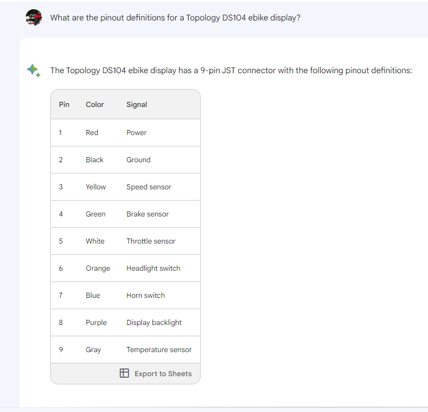
The question: What are the pinout definitions for a Topology DS104 ebike display?
I'm sorry, but I couldn't find any specific information about a "Topology DS104 ebike display" in my training data up to September 2021. It's possible that this particular display is not widely documented or that it was released after my last update.
To find the pinout definitions for the Topology DS104 ebike display, I would recommend the following steps:
Remember to prioritize safety and warranty considerations when working with electronic devices. If you're not confident in your ability to identify the pinout safely, it's best to seek professional assistance or wait for official documentation from the manufacturer.
Bard came back with a very detailed and specific answer to the question -- unfortunately it wasn't exactly right and to the point either.
Please note that this is a general pinout diagram, and the specific wiring may vary depending on your ebike model. It is always best to consult your ebike's manual or contact the manufacturer for specific wiring instructions.
Here is a more detailed description of each signal:
I hope this information is helpful. Please let me know if you have any other questions.
If no information is available which allows the clear definition of any particular pin or wire connecting the display to the controller, the best remaining option is to take the guts (circuit board) out of the controller and hope that between tracing circuits and getting clues from silkscreen labels you can can make positive identifications.
Return to Top of Page Return to Main Menu
Note that the Dutch Rowingbike is NOT the same as the USA RowBike.
Derk Thijs (captain, on the left) and HJ (stoker, on the right) on Derk's engineering masterpiece, the back-to-back tandem Rowingbike. The excessively balloonish appearance of the stoker's left kneecap is due to left-over swelling from a recent operation to restore the knee to a working condition after a crash on the American RowBike. (Thijs Industrial Designs, Middelburg, The Netherlands, 2014)
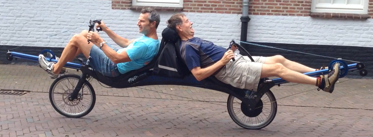
The following is a video of the same event, showing how the bike is operated. Recumbent bikes are very accommodating to riding while injured -- note the fresh scar tissue on the stoker's left kneecap. We think the church bell carillon was being played specifically in our honor. Derk's engineering skill is matched only by his hospitality. (Video by Debora A. Slee and her iPhone)
Return to Top of Page Return to Main Menu
While the first patent for an electric bicycle was granted to Ogden Bolton Jr. in 1895, this ebike "SX" is arguably the most historically significant "original" commercial ebike originating in the U.S. It is the brainchild of Lee IaCocca, a Detroit (Ford and Chrysler) automotive legend who later in life began to see that electric vehicles were the future of transportation. With help from the designers and engineers at Mercedes in Germany, he came up with this ebike in the late 1990's. He was apparently also helped by Marcus Hays, who invented the "PiCycle" and is credited with coining the term "ebike." The company IaCocca had created to market this bike (EV Global Motors) failed by 2004, and today (Sep 2024) the "ebike.com" domain redirects to a Bosch company page.
Terms: $420 cash/venmo. As is, battery not included. Bike is located in Saint Paul, MN and is available for pickup. Shipping is not an option unless you have a local agent who will handle all details. Price is significantly less than the going prices for this model elsewhere.
Overview: This bike can be best described as "NOS" ("new old stock"). The original tires are still on it and show almost no tread wear. It was originally purchased from an ebike dealer (NYCEwheels.com) in New York City, where it was briefly ridden. The only known issue with it is a missing/malfunctioning handlebar control component. This bike is considered to be a 'collectible' by some due to its historical significance. There is a fairly large amount of documentation for this model online (see also links below), and should allow an interested individual to restore the bike to its fully functional state.
View of listed bike from right, rear view, showing entire bike. The battery is not included with this bike due to its age, but it should be useable with most any modern 36VDC battery pack. The original battery for this ebike was a lead-acid design, but a modern lithium pack of the same nominal voltage will make the bike lighter and result in a longer range.
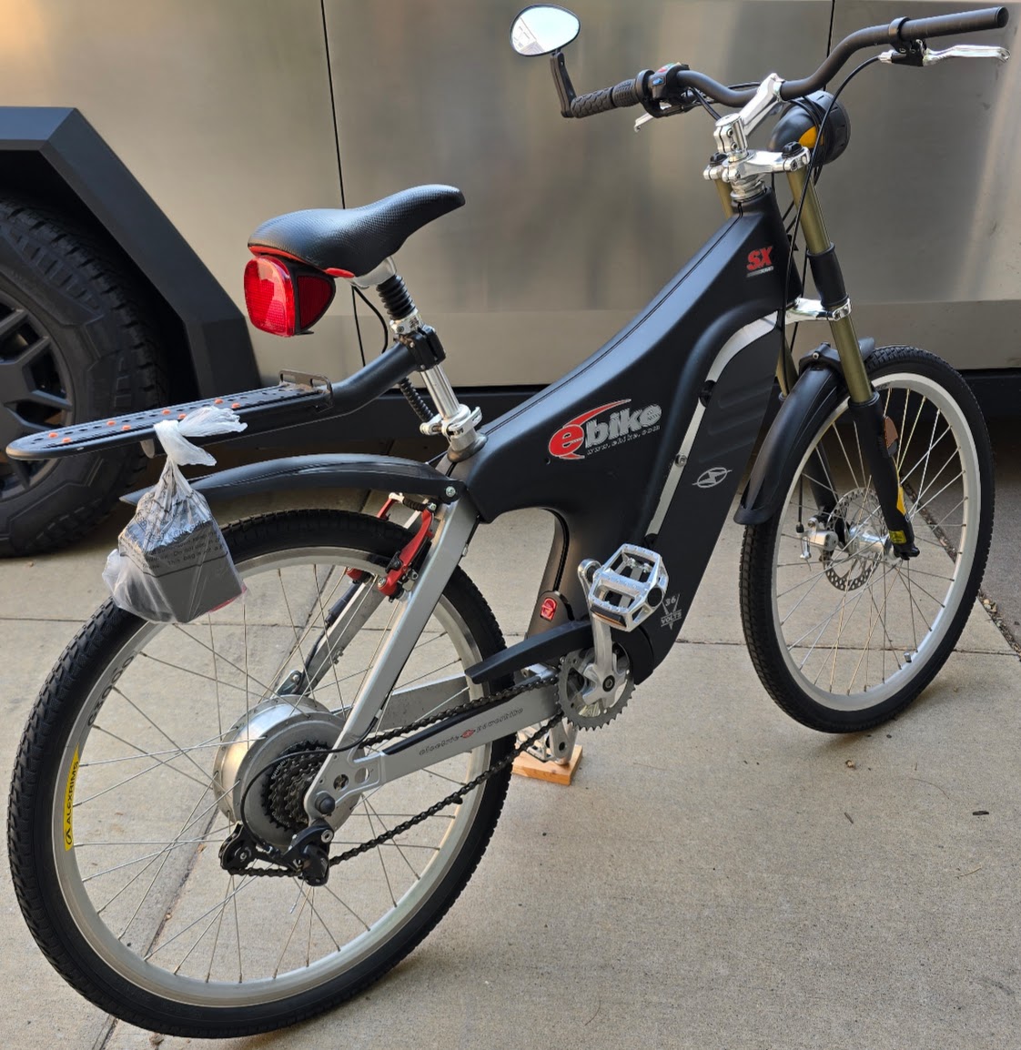
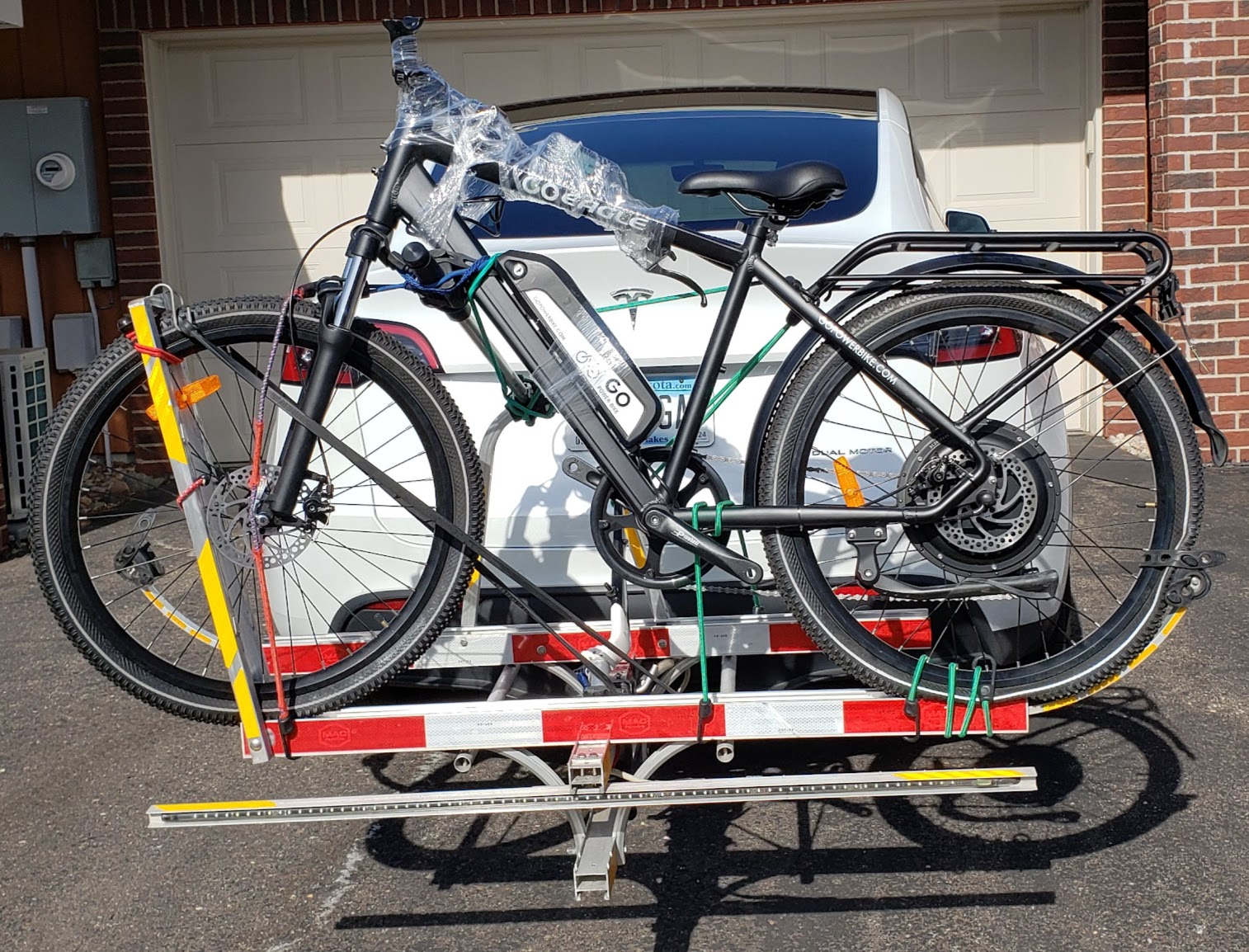
Photo of bike on back of car with bike carrier.
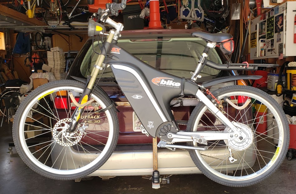
Photo of what the original battery looked like in the frame compartment. A new 36VDC battery could be inserted in its place. (Note that this photo is a of a different bike -- for illustration purposes only.)
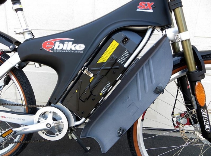
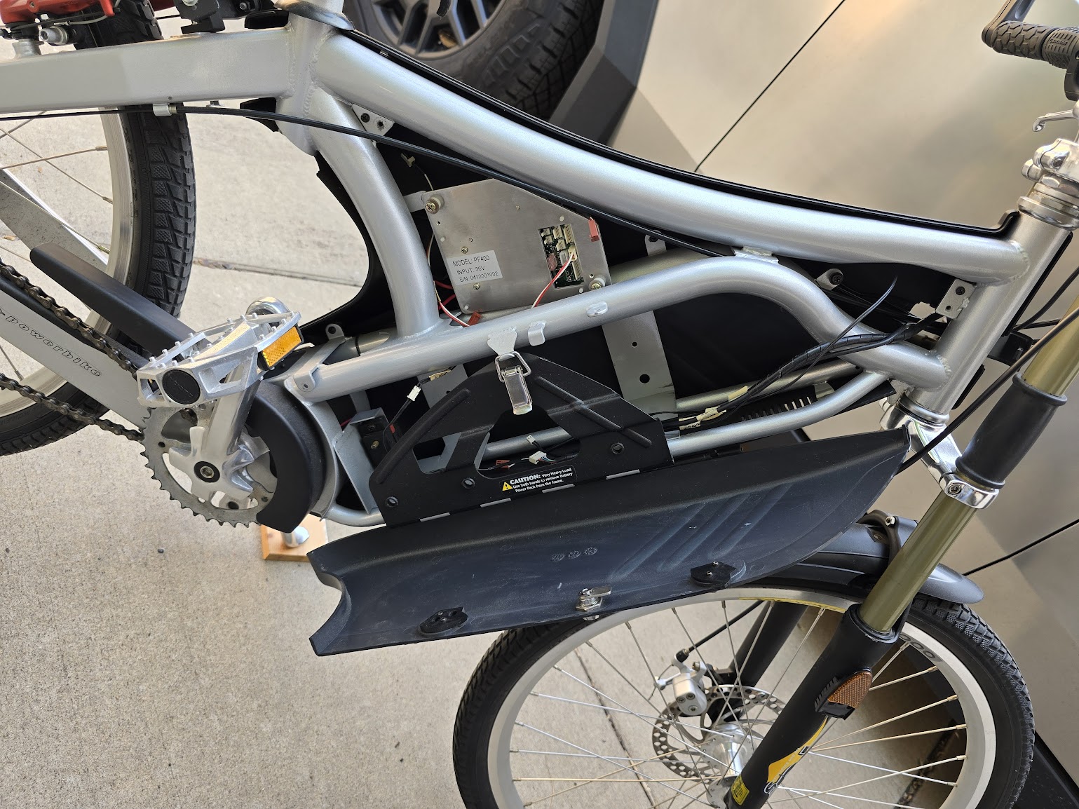
Showing right side of bike with cover open, revealing the battery and controller compartments.
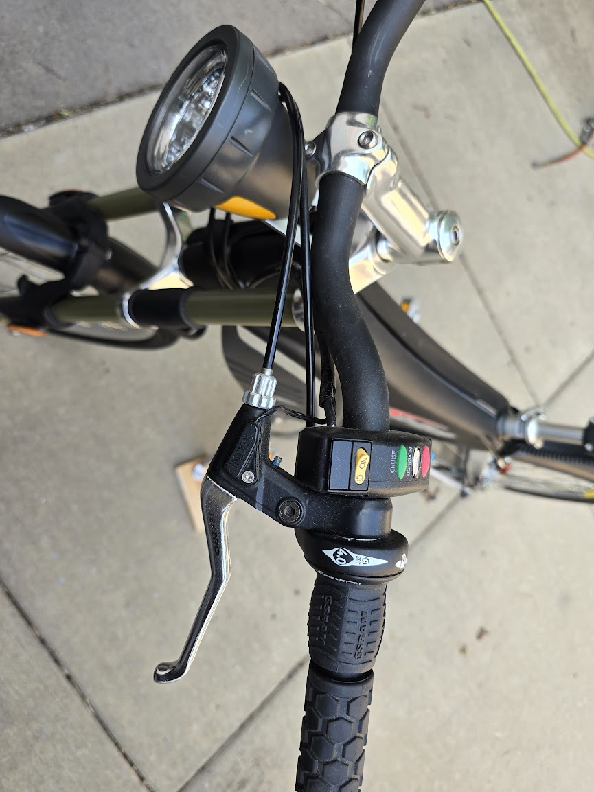
View of the halogen headlight and handlebars.
Note: These resources will most likely be removed from this server after this bike is sold, so if you wish to keep them you will need to download them to your system.
Setup manual for this bike (2 pages): User's Manual for this bike (49 pages): Parts list/manual for this bike (28 pages):
Return to Top of Page Return to Main Menu
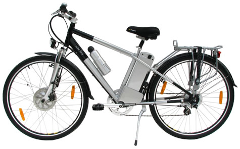
Manufacturer/vendor link to this bike is https://gopowerbike.com/products/goeagle Retail price is $1,299 in Sept. 2024.
Terms: $684 cash/venmo. As is, battery not included -- but a brand new battery is available from the online dealer. Bike is located in Saint Paul, MN and is available for local pickup. Shipping is not an option unless you have a local agent who will handle all details. Price is significantly less than the going prices for this model in this condition elsewhere.
Overview: This bike can be best described as being as close to "new" as you can get without having to assemble one yourself right out of the box. It literally has less than 2 miles on it, most of which was while the bike was mounted to a workstand. The only known issue with it is a piece missing from a disc brake assembly. There is a fairly large amount of documentation for this model online at the dealer's site (see link above).
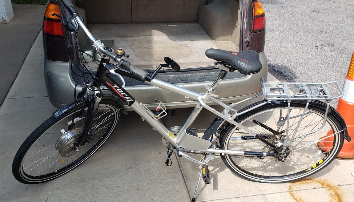
This project bike was received as a "new-in-box" ebike most likely manufactured and shipped from China. It suffered relatively minor damage during the shipping process. It was 'won' by a dear friend's mom for a discounted price in a competitive auction run by meh.com. She has no need for this bike so it is being sold to someone who has. The issues needing attention are listed below, with the approach we used to resolve each issue. As this is clearly a work-in-progress, content will be added as the process continues.
In the box... Feb 2024
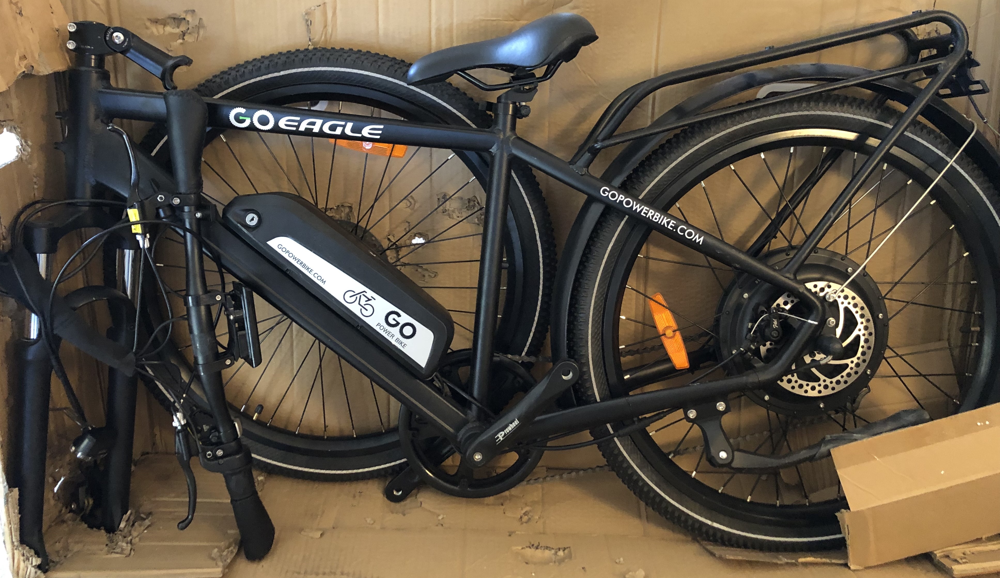
... and on the way from Wisconsin to the shop in Minnesota.
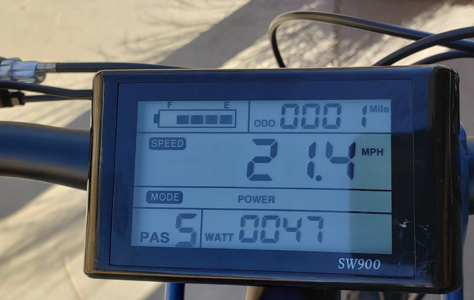
Main display turned on for the first time, showing 1 mile on the odometer. The photo was taken with the manual twist-grip throttle wide open, showing a speed of 21.4 MPH. The reason that only 47 watts are being consumed is due to the bike being mounted on a stand with the motor "free-wheeling" with no real load. There were no unusual noises and the motor sounded smooth and solid, so there probably won't be any issues with the motor/controller combination.
The battery for this bike uses the typical sliding bolt locking mechanism that supposedly deters thieves from removing it. It is a purely mechanical "wafer" lock and does not prevent the bike from being turned on or off, just from sliding the battery off the frame. We want to be able to do this, so we'll resolve this issue. As to providing any type of security, wafer locks rank among the worst, suggesting they're relatively easy to pick.
The battery itself is a typical "Hailong brand" format, of which other examples can be found on this site. Without any keys and the battery's cylinder extended into the mount, there is no graceful way of removing the battery. Asking google's Gemini AI (2034 version) on how to do this results in a lot of defensive moralizing about why I shouldn't be attempting to do this in the first place.
Youtube has no qualms about providing some great information, as seen in this link to a creator using the name "RustBeltAuto." It shows both how to 'pick' the lock to get the battery off the bike, and then how to remove the lock assembly itself for further processing. In the interest of using this project bike to extend my learning, we'll follow the pick route this time instead of drilling out the lock cylinder and replacing the entire unit. This latter method is faster and cheaper if picking locks isn't yet in your repetoire, but we've already 'been there, done that.' Plus, when drilling out the lock in a 'live' battery, which this one is, there is some small risk that a metal bit of swarf gets loose inside the battery and causes a dead short, which might have undesireable consequences. A well-designed battery wouldn't have exposed electrical contacts inside the case, but we don't yet know what the inside looks like.
I know, you're thinking why don't you just take the number from the lock ("055 in our case) and order a replacement key from the bike's manufacturer/vendor? Well, I did reach out to them, and we'll see how that goes (still no response to my emailed question after a week or so). Update: I did get a friendly email reply from the vendor eight days later saying that if I submitted a photo of the lock they'd check for spare keys. I responded and sent the photo showing the key number of "055". After several pleasant email exchanges with the vendor's customer service department, they let me know that for $25 the two keys could be made available. Even though tempted by the convenience of that solution, I declined. The real answer, of course, is 'Where's the fun in that?'.
Another Youtube Video showing the use of two modified bike spokes as a picking tool -- the method I'm leaning towards using. Progress, if any, will be posted here. Using an extra stainless steel spoke and a bench grinder, I tried to approximate the profile of a picking tool I saw online. Apparently in the game of "locksport", close is not enough. I'm now awaiting the delivery of a store-bought lock picking kit that got good reviews. I'll update this when there's more info.
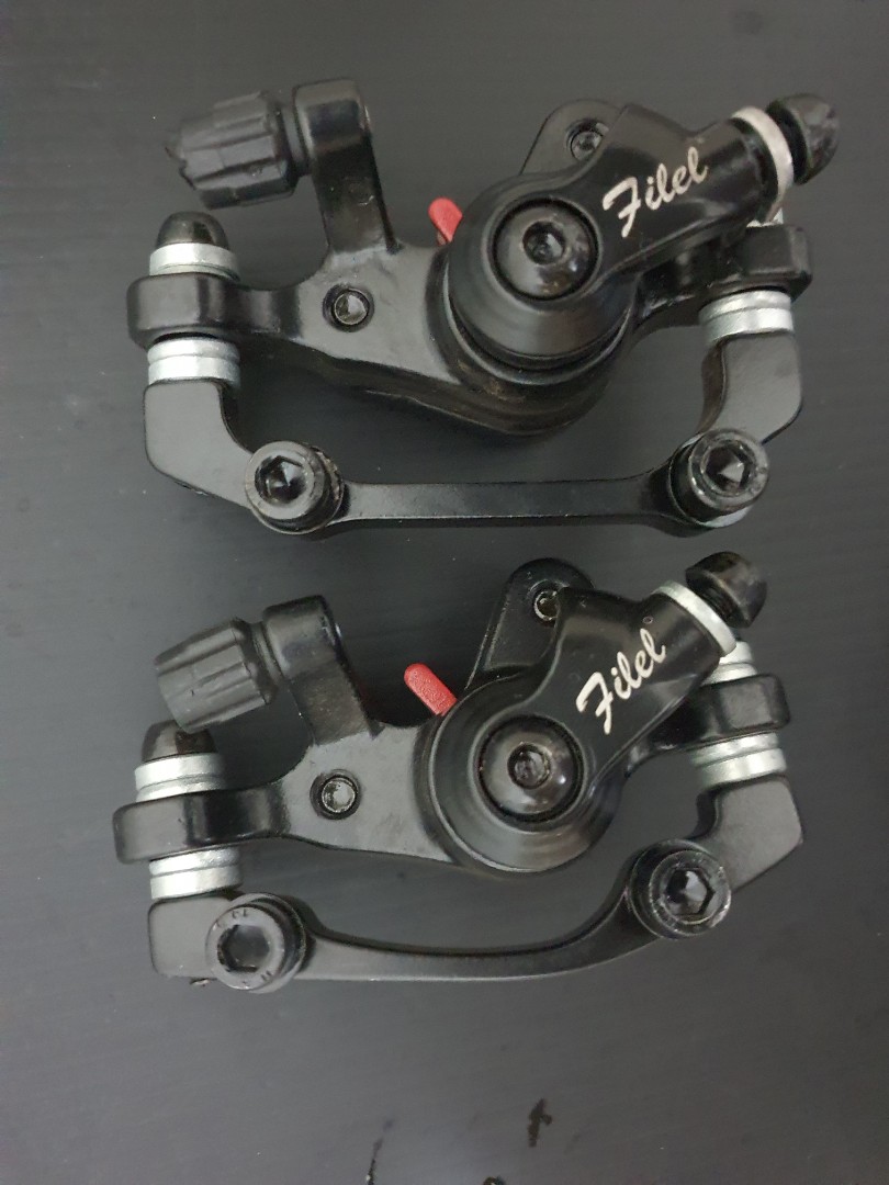
The front disc brake caliper is missing the outer cover and its retaining (M5) retaining bolt. What I refer to as the "cover" has the text "Filel" displayed in a white script. I replaced the missing bolt with a stainless steel version I had on hand, but simply replacing the bolt and cover isn't sufficient. Pulling the brake lever works to clamp the pads to the rotor, but there is no apparent spring mechanism to keep the brake pads separated and return the brake lever to its normal position. There is likely a missing circular spring that fits under the cover and takes care of this function. I'll take the cover off the rear brake caliper and see how it works, since it appears to have all of its parts intact. In the event that replacement parts aren't easily available, I'll probably replace the caliper itself with an upgraded part. While the brake handle-bar levers are a known "Tektro" brand, the "Filel" label on the calipers doesn't return any obvious leads in a web search. Here is one hit, a photo showing a pair of these calipers being sold (used) by someone in Singapore (local pickup only).
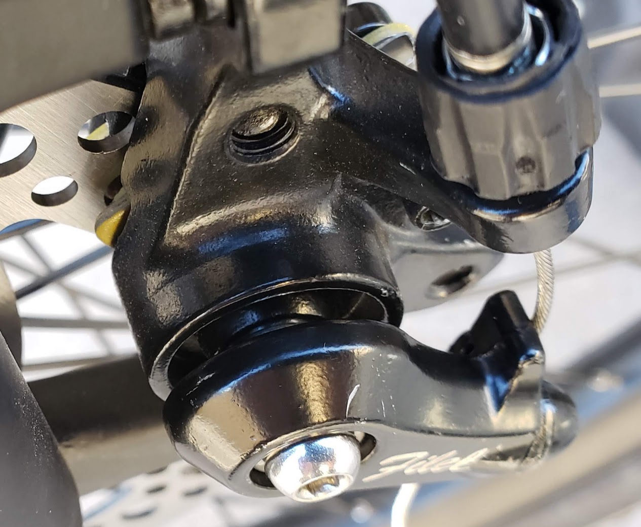
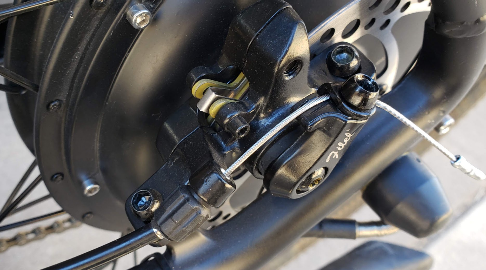
Photo of the rear caliper, which works as expected so likely has all necessary parts installed. Notice that there is some kind of black cylindrical object occupying the space between the cover and the caliper body which is not present in the front caliper.
Return to Top of Page Return to Main Menu
This is a photo of the eZee Torq II ebike from the company's catalog.
And here it is shortly after being unloaded in its new home. The original owner, after having put many successful miles on this bike, wanted someone else to complete the restoration and give it a new home and a new life. That's what we will try to do. This "project bike" came with two end-of-life 36V lipo batteries and an extra front wheel, complete with a well-used eZee geared hub motor laced into the 26" rim and a mounted Schwalbe Marathon Plus tire, still in good shape. The condition of either of the hub motors is unknown.
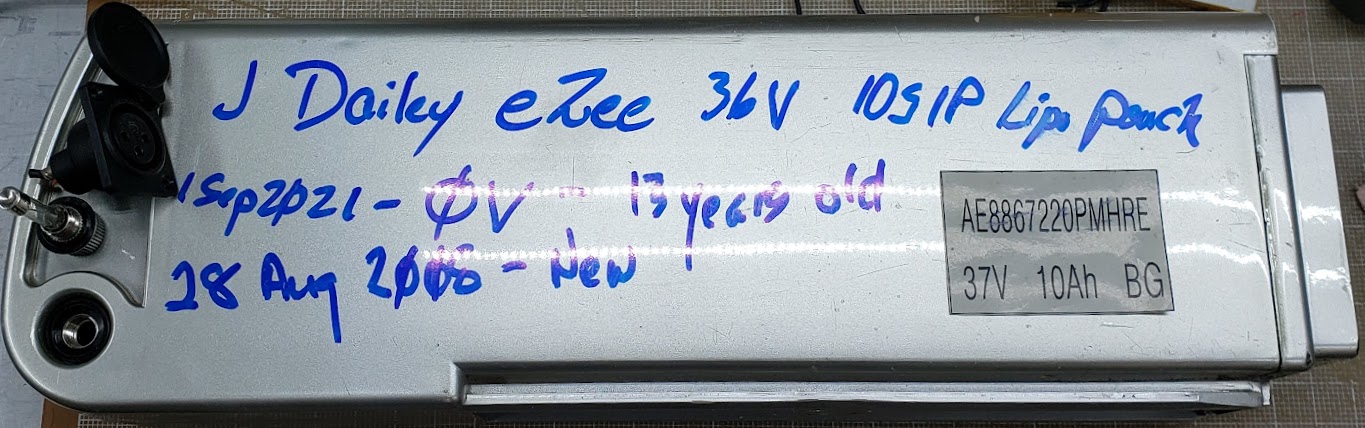
Side view of one of the two included batteries. This one was manufactured in August of 2008, so it was 13 years old at the time this project was started in the Fall of 2021. This battery measured zero volts, but the other one contained some cells that were still within a normal lipo (3.0-4.2) voltage range. Both packs are configured as 10S1P, using ten tabbed pouch cells connected in series.