This page's link: "erowbike.com/controllers"
Return to Main Menu
Documentation for motor Controllers
| Brushless 3 Phase DC (BLDC) & ESC types |
| Phaserunner |
This section documents our use of the Grin Technologies Phaserunner BLDC FOC controllers. |
| Grinfineon |
This section documents the Grin Technologies Grinfineon BLDC FOC controllers. |
| Infineon by Lyen |
This section documents the Infineon controllers modified by Ed Lyen to allow more power to be used. |
|
Generic Infineon
|
This documents the 'generic chinese' Infineon controllers, typically supplied with absolutely no documentation.
|
|
Infineon "K" Series
|
Document the subset of the generic chinese Infineon controllers that support a basic display for the user.
|
| JPods BaseBoard |
Notes for the "BaseBoard" PC board developed by JPods as a master control board for bogies. |
| VESC Controllers |
This section documents the ESC controllers developed by Benjamin Vedder ("V"+ESC) of Sweden and open-sourced. |
| Controller Repair |
How to diagnose and repair BLDC motor controllers. |
| Controller Resources |
Links to a variety of aids to better understanding motor controllers. |
Phaserunner
Typical Specs:
FOC, up to DC 90 volts, 3,600 watts, 40 amps continuous/90A peak; up to 60,000 eRPM (physical motor RPM multiplied by the motor's pole pair count). These specs generally apply to the post-beta, BAC 8000 potted units from Grin.
Catalog page for Phaserunner on Grin Tech site
Designed and manufactured by Justin Lemire-Elmore of Grin Technologies [ebikes.ca] in Vancouver, BC; info@ebikes.ca (Justin prefers email over PM's on endlessphere.com;)
Photos of multiple versions of the Phaserunner controller (some photos courtesy of Grin Technologies). The most obvious distinguishing characteristics are the cabling and connectors used to mate the controller with a specific BLDC motor.
Version 1, produced from Nov 2016 to Aug 2017. Bill James/JPods acquired the first two units of these Phaserunners for our joint projects in Aug 2016. We primarily paired these controllers with Alexey.K's RV-100 and RV-120 BLDC motors.
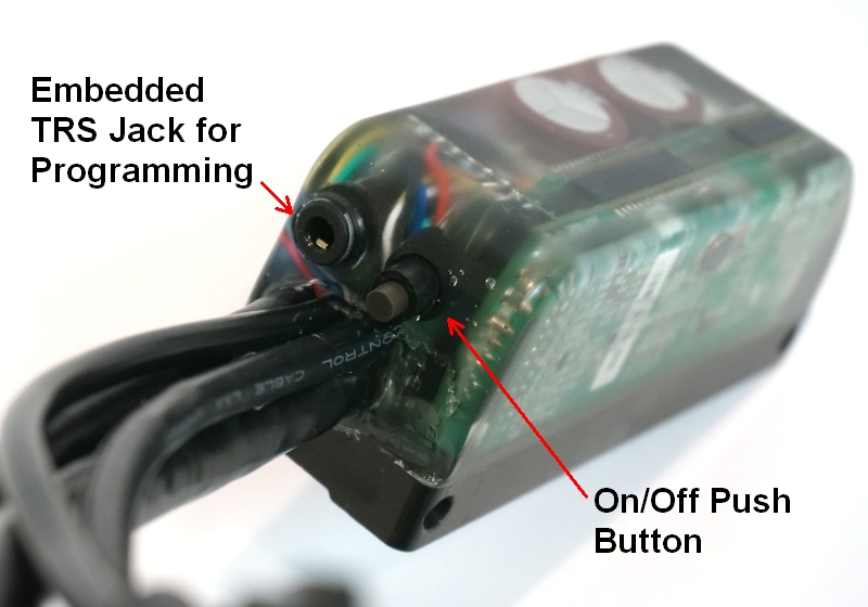
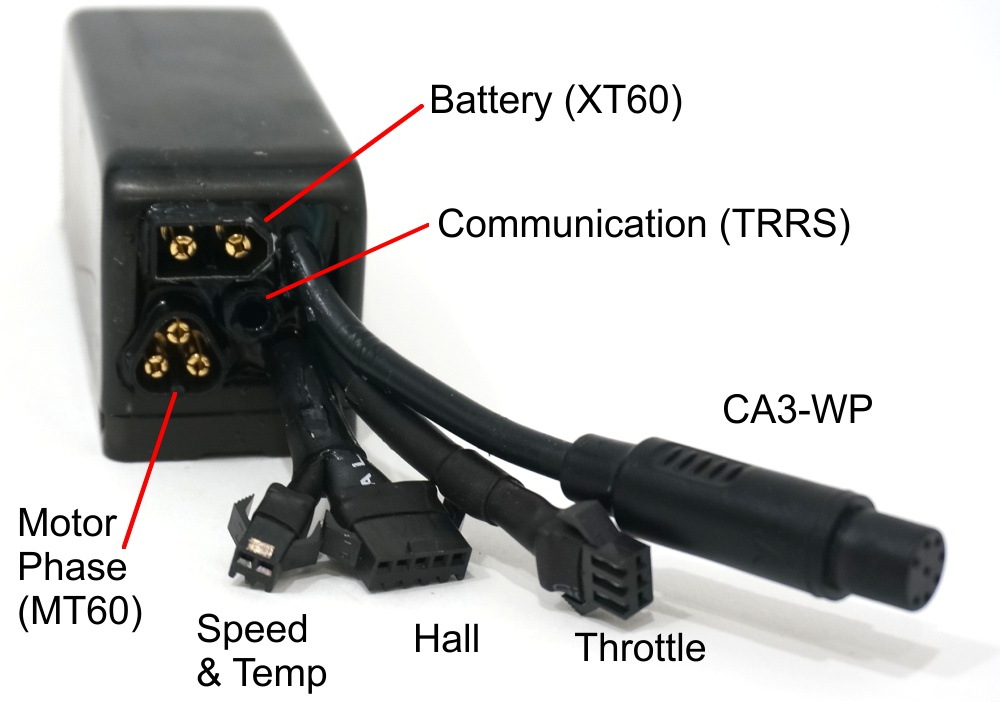
Version 3, split into different sub-models depending on cabling and connector options. The XT60 connectors used have pins and sockets with a 3 mm diameter. Note that the communications/programming port on these newer Phaserunners have an extra 'sleeve' connector (TRSS vs. TRS), which supplies 5VDC.
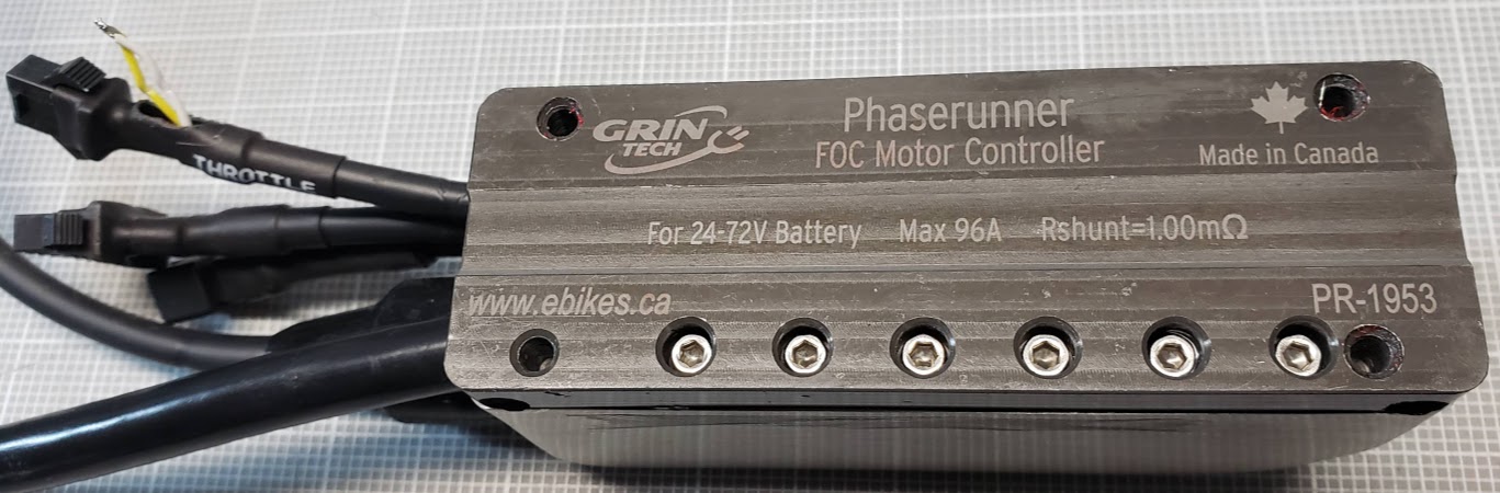
Version 3, bottom view. You can also see the yellow and white wires peeled out of the Throttle cable harness where they had been hidden at the factory. By default they are shorted together, resulting in the controller being ON whenever the minimum voltage is applied to the battery input terminals. If, as here, they are exposed and a SPST is inserted, that switch will function as an ON/OFF switch.
Software/Programming
The Phaserunner is based on the ASI (Toronto) manufactured BAC8000 controller, which used the "Bacdoor" software to program the controller's operating parameters and run the "Autotune" procedure to match the controller to a particular motor -- the actual motor, not just it's model or type. Justin at Grin redesigned the circuit board to fit into a smaller form factor, added better wiring and switches, heatsinks, and potted the entire controller.
Main thread on Endless Sphere (ES) forum: includes links to Firmware and Programming (Setup utility, FTDI drivers, etc.)
Phaserunner on ES
Using the Phaserunner software, on ES
Justin: "There is a lot of talk about sinusoidal and field oriented controllers ("FOC")
on this board
which is a good thing to finally see happen. Both sinusoidal and FOC controllers run brushless motors silently with no hum or buzz, but a FOC by definition also automates the phase advance process so that the motor is driven at optimal timing even at very high RPMs. This makes them work well over a broad range of motor types and as a result this has been our go-to controller source for all our interesting EV projects."
Justin's updated GUI controller software can be downloaded at the following links:
Windows
Linux
(MacOS version just going through some adjustments)
Return to Top of Page
Phaserunner & Crystalyte 3525
First test run 16 Sep 2016; I made an adapter for the Hall sensor mini 5 pin plug on the 3525 to mate
with the 'standard' Grin JST-SM-5 Hall connector, where pin 1 is GROUND and pin 5 is +5VDC.
The Phaserunner phase wires didn't match the Crystalyte's wire colors, so I swapped the YEL and BLU
outside wires on the Phaserunner side (GRN remained the middle phase wire on both sides).
This did NOT work. The static spin test just had the wheel do a violent "shudder" (no rotations).
I got an erroneous result screen with a "Kv" value of 1.54 RPM/V, and "Warning: Invalid hall sensors!
Running sensorless. Hall Offset 0 degrees". I did forget to set the parameters to use the Hall sensors,
but that didn't really seem to make a difference when I corrected that and re-ran the Autotune.
I then switched the BLU and YEL phase wires back to their original positions on the Phaserunner and re-ran
the Autotune, selected "Hall sensors" (on start and run -- Grin recommends Start with sensors, but RUN
sensorless, will try that next). This time the Autotune finished without any errors, and everything
seemed to work fine. The speed in the dashboard display seemed too low with WOT, but the Sigma indicated
a ground speed of 22.8MPH, which is right where it should be. This is using the default "Torque" throttle
with my pill bottle throttle control, so the "loaded" speed may differ.
Note that when using the Lyen Infineon controller, we also switch the BLU and YEL wires, so maybe it's
important to connect the phase wires "Infineon" style, even on the Phaserunner. I thought it auto-detected
all of the wire connections.... will need to confirm that.
To begin with, I've left all other settings at their defaults.
Return to Top of Page
Infineon by Lyen
This is the very first controller we got to build the erowbike1 prototype, using the Crystalyte rear hub motor. We're currently using this controller on the BogieDyno to test generic Infineon controller compatibility. Ed Lyen starts out with a standard Infineon controller and replaces/adds/improves MOSFETs and makes other board modifications that make these controllers to handle much larger currents.
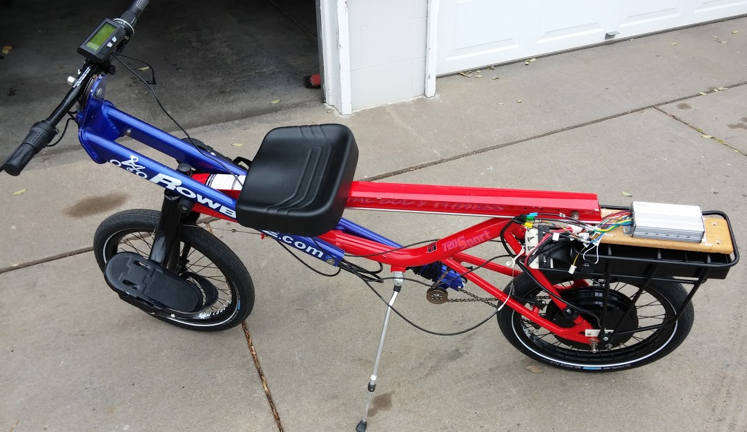
In the following photo from November, 2013, you can see the Lyen controller mounted on a board on the rear rack, above the eZee Flatpack 13A/48V traction battery.
Return to Top of Page
Infineon - "K" Series
This covers the somewhat generic version of the chinese made "K" series Infineon controllers. These will mate with the K* LED displays that provide the functionality of a bike computer in addition to the electrical info such as battery levels. The main distinction between all of these generic infineon controllers is that the ones rated for higher power levels will have more and/or better MOSFETs (e.g., 12 vs 6), and those for higher voltages (e.g. 48V vs 36V) will use electrolytic smoothing capacitors with correspondingly higher ratings. Knowing this, if you end up with a controller without proper labeling, you can make some reasonable assumptions about its design specifactions. The higher quality controllers will use MOSFETs that are more reliable and efficient. One relevant parameter for power MOSFET's is their mOhm (milliOhm) rating, where lower is better. Stock MOSFET's might have a 10 mOhm spec, while higher quality units may be rated at 6 mOhms. Find the "IRF*" number on the chips and look up their datasheets to obtain this information.
The photos here are courtesy of the russian website electrotransport.ru . Just search the site for "Ќонтроллер Infineon" -- where the cyrillic (russian) sript is translated as "Controller". [ Ќонтроллер] If, in the unlikely event you aren't fluent in Russian, you can resort to the google translate feature and experience the current state of AI skills.
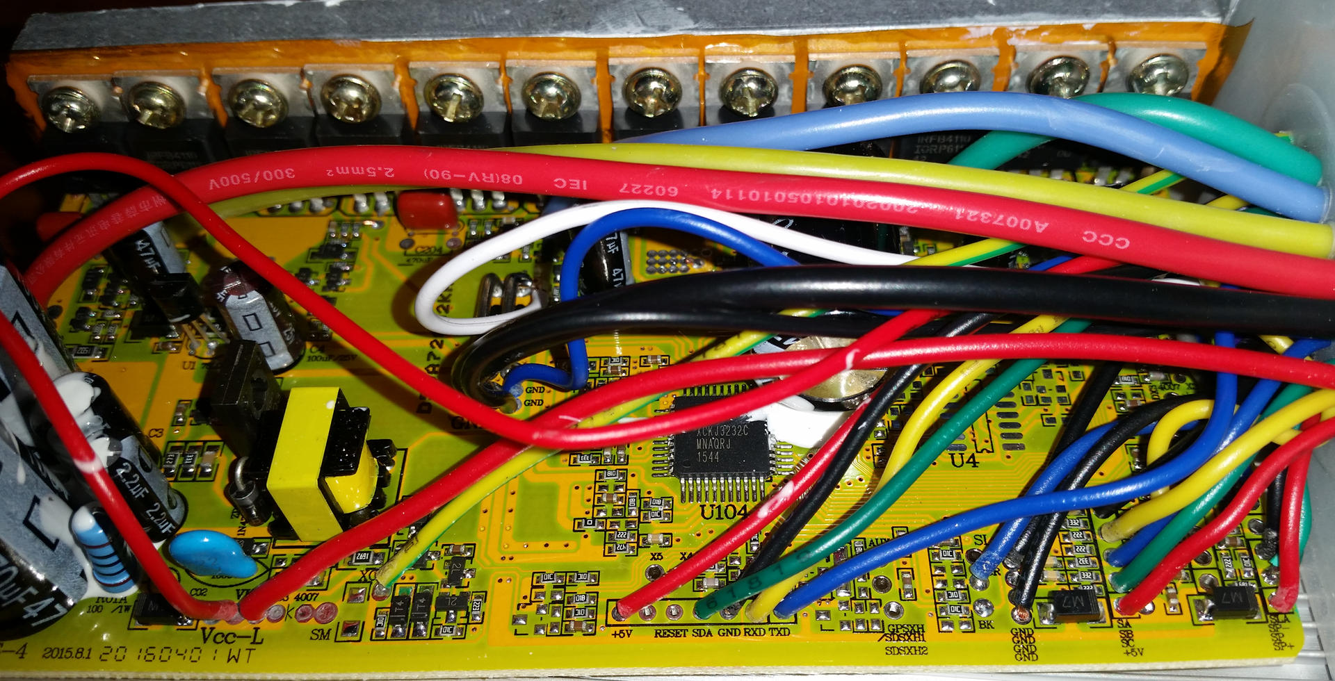
The part of the controller's main board seen above shows the ports where the five programming cables (red, green, black, yellow, and blue) are attached.
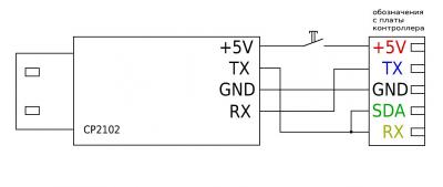
The schematic below shows the proper wire connections in the USB cable end connected to the computer when programming the "K" and other Infineon controllers. As is common with serial communications between a device and a computer, the blue transmit (TXD/TX) and yellow receive (RXD/RD) signals are crossed, while the red 5VDC+ power and black ground wires go straight through.
Note that the yellow RX/receive and the green SDA signals are jumpered on the controller side in the programming cable. By convention we have used JST-SM-5(M/F) connectors to allow the removal of the programming cable when not required. The on/off switch in the power line of the programming cable is optional. The programming software used is the "XPD" app.
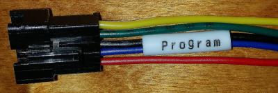
This shows the JST-SM-5 male plug as it would be attached to the controller. These wires simply correspond to those shown above attached to the controller's PCB.
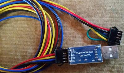
This shows the mating JST-SM-5 female connector used to connect the programming cable to the controller. Both the crossing of the TX/RX lines and the SDA jumpering occur here. The USB plug going into the computer also shows a USB-TTL (Serial) UART converter attached inline. This is also a generic part and usually works fine as long as the computer's OS has the right driver installed. If the computer 'recognizes' the programming cable when plugged in and matches it to an available "COM" port, you're usually good-to-go.
Return to Top of Page
Grinfineon
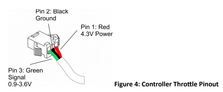
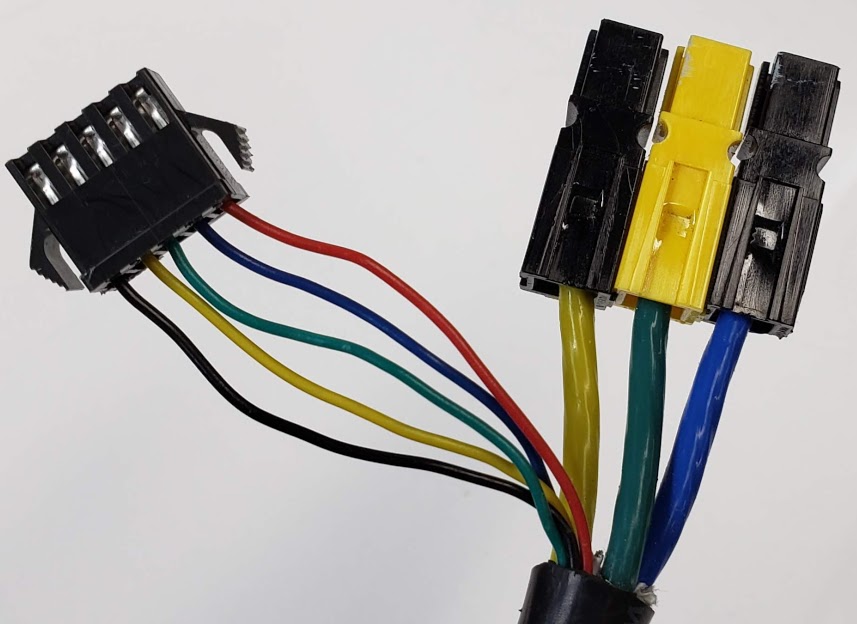
The Grinfineon controllers we have all used the JST-SM-F(emale) series connectors for data/signal lines. The traction battery pack and motor phase wires used Anderson PowerPole connectors, typically with the 45 amp pins. (Diagrams courtesy of Grin Technologies, Grinfineon manual v 2.2, 2018)
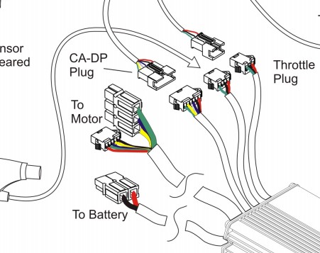
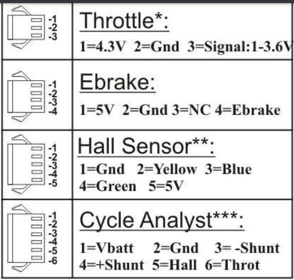
The following diagram shows the pin assignments for all of the signal socket connectors. Note that in most cases only pins 2 (Ground) and 4 (ebrake Signal) are actually used in the four pin ebrake connector. Pin 1 (+5VDC) is generally not needed because the ebrake signal (Pin 4) is pulled high internally ("active high"), and only needs to be shorted to pin 2 (Ground) to activate the ebrake circuit.
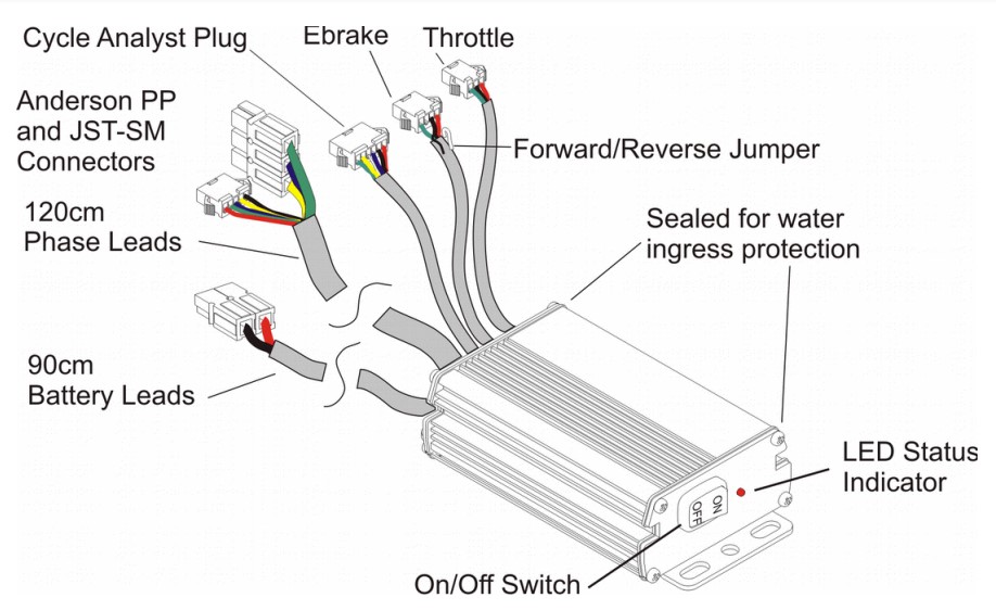
This drawing is representative of all the various members of the Grinfineon controller family. It is also representative of the signal wires and connectors used on the early Phaserunner controllers. This diagram also shows the white FWD/REV wire, as well as the "for future use" purple wire, tucked into the ebrake cable bundle (although I've typically found these wires in the throttle bundle!).
The sinewave (newer) versions of this controller are based on the popular Xie Chang controllers using the XCKJ3232C chip, but with custom firmware to allow both sensored and sensorless operation, as well as proportional regenerative e-braking.
See Grin's online info for the Grinfineon controllers for the complete documentation for this controller series. We typically use the 48 volt DC, 1500 watt, 45 amp versions.
This is an Infineon type controller designed and built by Grin with enhanced capabilities. Unfortunately, this controller's parameters are not configurable via a programming app. Note that there are multiple versions of the Grinfineon controller. We don't address the pre-2013 Grinfineons here. All Grinfineons support running BLDC motors either with or without the presence of Hall sensors. In other words, they are all capable of running in sensored or sensorless modes. However, the "original" Grinfineon, made from 2013 through 2016, operated only in trapezoidal (vs the "better" sinusoidal) mode. There are advantages to using motors equipped with Hall sensors. When operating with hall sensors, the newer Grinfineon controllers use a sinusoidal output waveform which runs most motors more smoothly and quietly than conventional trapezoidal mode controllers would. This is especially true if you expect to start an LEV under a heavy load, with full assistance right at the beginning.
This series of controllers supports a REVERSE switch via a FWD/REV (white) wire hidden in the throttle wire bundle sheath. Short this FWD/REV wire to ground to enable reverse. There is also a purple wire hidden in the same throttle wire bundle, which can be used for (temperature data?) Per the official manual for the original Grinfineon, we have the following explanation:
Note that there is also a purple wire under the shrink wrap too. This is reserved
for future functionality and is not a ground wire. Connecting the white to purple
will not change direction; you must connect it to a black (ground) wire.
It also natively supports proportional regen (see below).
Grinfineons report their operating status via a small red LED near the ON/OFF switch. A steady 0.8 second ("slow") on/off flash pattern means all systems are ready to go. Once the throttle is engaged, then then the LED will either stay steady ON if it is running in sensored mode, or it will blink at a faster 2Hz (twice a second) rate if it is running in sensorless mode. Note that the controller LED will always blink slowly at 0.8 Hz when the throttle is disengaged and everything is OK. It is only when you have the throttle engaged and the motor turning that you will see the steady ON led indicating sensored mode is active.
A different repeated flash sequence followed by a pause indicates a status or fault condition. The "status" codes are shown below (see the online documentation for the "fault" codes).
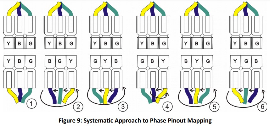
Phase Mapping Procedure
The Grinfineon controllers do NOT ship with the phase wires arranged in the same order as 'stock' Infineon controllers. The firmware in the Grinfineon supports auto-detection and mapping of the phase wires, so normally this shouldn't matter. If the motor's rotation is wrong, swapping any two adjacent phase wires will reverse the rotation.
This section needs more research and clarification:
The following is an excerpt from the Grinfineon manual for the 'new' sinewave Grinfineons suggests that these no longer "auto-map" Hall and phase wires:
Since the Grinfineons we have don't really have model/serial numbers, apparently we'll have to experiment with each controller to see what is capable of...
This diagram shows how to rotate through the six possible combinations of phase wires between the controller (top of diagram) and the motor (bottom of diagram).
Hall Mapping Procedure
The following indented paragraphs are quoted directly from the Grinfineon documentation (emphasis added):
Traditionally, figuring out the proper hall/phase pinout between a given motor and controller was a tedious process of trial and error, with 36 possible hall and phase pinout combinations only 3 of which would spin the motor correctly in the right direction. With the Grinfineon controllers, this hall pinout can be mapped automatically by the controller.
To do this, first power up and run the controller with the halls unplugged and with the motor off the ground. You should notice that the controller LED flashes in a rapid 2 Hz blinking pattern while the motor is spinning, which indicates that it is in sensorless mode. Running sensorless like this clears out any previous hall mapping from the controller memory.
Next, connect the hall plug between the controller and motor. Now run the motor again, and apply and release the throttle several times. When the controller has determined that a valid set of hall signals is present, then the LED will switch from a rapid 2Hz blinking pattern to being steady ON when the motor is running. This confirms that the controller has mapped and is using the hall sensors for commutating.
Note that this mapping procedure can also be use to test the status of the motor's Hall sensors. Even if not using the Hall's sensors for smoother operation, they can supply the RPM/speed data.
Hall Timing: 120 vs 60 degrees
Timing refers to the the number of degrees between the rising edge signal generated by each of the three Hall sensors in the motor. A Hall sensor is turned on ("high", or "1") when the north pole of a magnet, glued to the spinning rotor, passes close by. A Hall sensor turns off ("low", or "0") when it's exposed to a subsequent magnet's south pole passing by. These actions result in a series of pulses sent to the controller, which then can more effectively know where the motor's rotor and stator are in relation to each other. The following indented paragraphs are quoted directly from the Grinfineon documentation (v 2.2, 2018):
Most brushless motors use 120 degree hall timing, where at any given point there is always at least 1 hall signal that is high, and 1 hall signal that is low. But some motors use 60 degree hall spacing, where 000 and 111 are also valid hall patterns. ... The Grinfineon controller will map to 60 degree hall timing, but once this is done it is tricky to reset the mapping for it to run sensorless as having the halls unplugged will produce what appears to be a valid hall signal.
The Sine Wave Grinfineon controller will not work in sensored modes with brushless motors that have 60 degree hall timing. If your motor has 60 degree halls, then you will have to run it sensorless and leave the halls unplugged.
Throttle/Regen
The positive voltage supplied on pin 1 of the throttle connector is not the full 5VDC is because it is downstream from a diode inside the Grinfineon. This diode accounts for the 0.7V drop. The 0.9-3.6V range is the active 'forward' throttle range provided by the typical resistive or Hall Effect throttles used in LEVs. A simple 5-10K pot (potentiometer) would provide the same functionality, except that its range would be closer to 0-4.3 volts. We use such pots in place of a stock throttle when testing regen performance. When used like this, the pot simulates a "bi-directional" throttle, because it can also operate in the 'reverse' 0-0.8V range.
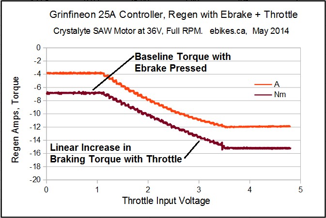
On all Grinfineon controllers, the 0.0 to 0.8V throttle range is mapped into a proportional regen mode, so the lower your throttle voltage goes below 0.8V the more regen you get. With a true "bi-directional" throttle this allows you to "reverse" the throttle and slow the vehicle. This bi-directional throttle requires that if left untouched it outputs between approximately 0.9 and 1.1 volts. With the use of CA3 these values can be adjusted as necessary.
Alternatively, you can also activate the ebrake, and while ebrake is "ON", increasing the throttle will increase the amount of regen.
Return to Top of Page
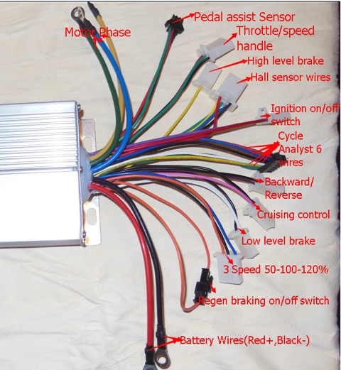
Generic Infineon
Controller used here as an example of this category:
Batch: GT20140802-02-15G15;
DC 36-84 volt, 1500watt, 45 amp
Wiring Color Codes
Remember that if you're dealing with a "smart" controller, such as the Phaserunner, it can figure out which motor wires serve which purpose. Unfortunately, this pairing process usually requires some user effort with an app and a computing device. This is fine when you want to pair a motor with a controller for a long time, creating a monogamous relationship. In a prototyping environment, however, you're dealing with motors and controllers in polygamous relationships, and it's desireable to easily swap out components for testing purposes.
Ultimately, there is no 'standard' color coding scheme for either PHASE or HALL sensor wiring, since many motor manufacturers don't identify their BLDC motor wires to begin with. If they do, there is no guarantee that it will correspond to the controller you intend to use with that motor, unless you buy the two already paired. Fortunately, if the motor is supplied with Hall sensors, the DC supply wires to drive the Halls typically are identified as red and black. For our purposes, we try to identify all wires exiting the motor to correlate to the generic Infineon wiring standard, such as it is (or isn't). The idea is that for testing purposes, we can connect any BLDC motor to the Infineon controller on the BogieDyno and get it to spin in one direction or the other. Since the generic Infineon controllers aren't good at running in "sensorless" mode (no Hall sensors in the motor), we'll assume that all motors used in this context will have Hall sensors installed.
Once the wires are identified as to color, the next order of businessThe order of the wires becomes critical when they are combined in a multi-terminal plug. The Hall sensors on the motor side are almost always installed in a multi conductor plug, probably to make sure that the 5VDC power wires are connected in the right order. This means that the motor and controller Hall plugs must not only be physically compatible, but also electrically.
Phases: (order of preference??) A good mnemonic would be good to help remember putting phase and Hall wires in a specific order. The goal is to have the motor and the controller *each* have their Hall and phase wires identified so that a one-to-one connection scheme runs the motor as intended. If the rotation direction is 'wrong', many controllers have an on-board forward/reverse function that is brought out by two or more wires. Sometimes there are two white wires coming out of the controller, one with a male plug and the other with a mating female plug. This is sometimes referred to as the 'learning' pair of wires. By powering cycling the controller with the wires connected/disconnected, the controller can toggle the direction of the motor's rotation and learn/remember this setting for the future, even after many power on/off cycles.
Use Grin's Grinfineon plug order?
Y-G-B == "igbie"
B-G-Y == "biggie"
B-Y-G == "big"
G-B-Y == "gabby"
Halls: Ideally this follows the same order as the Phase wires:
On the Grinfineon/Phaserunner?? Hall connector [JST-SM-5F], this is as follows [where Black wire is pin #1]
BLACK-[Yellow-Green-Blue]-RED
(includes the 5VDC power leads on the outside terminals of the JST-5 connector)
Up to now, we have focused on identifying controller and motor wires using colors. If this system were applied according to industry standards, we'd be home free. However, if colors can't reliably be related to any particular wire's electrical function, then why bother? The following textarea box contains a 2012 post on ES by user "Kingfish" in which he proposes using a "Color-agnostic" system in which we identify each phase and Hall wire by its electrical function. While it originally contained some images which would likely have been helpful, they were no longer available when this was written in early 2021.
Since we're dealing here with only 3 phase BLDC motors and controllers, Kingfish uses "A,B,C" to functionally identify each wire. He also uses "channel" and "Phase ID" to refer to each wire's functional role. Once each motor's and each controller's phase and Hall wires are functionally identified, a single logical chart can be used to connect the motor and controller and we know that it will work.
Kingfish focuses on the use of 3 phase motors in ebikes, so he's concerned about whether any particular motor is for a front hub or a rear hub. This is relevant in the context of which direction a motor spins, and most ebikes only need to be powered in one direction. We also care about the motor's directional rotation, but often don't relate this to the motor's location in a non-bike LEV. We care only whether a motor will by default spin in a clockwise (CW) or counter-clockwise (CCW) direction. Since all 3 phase BLDC motors can spin in either direction, we only need to know how to reverse its direction if necessary in a particular application. Note that if the motor is assembled with a freewheel mechanism, it may only provide propulsion in one direction, even though it can spin in both directions. We have adopted the standard that CW or CCW is determined when facing the side of the motor from which the cables exit. We refer to this side as being the "face," "front," or "wire side" of the motor, regardless of how or where it is mounted.
Golden Motor to Infineon, color pattern:
From motor = Blue Green Yellow
To controller = Yellow Green Blue
I swapped yellow and blue on both the hall and phase wires.
or, second opinion:[difference between the HBS and the Magic Pie models?]
If it's based on the standard Infineon controller the wires should be the same as GM's:
Quote from: T5T on March 02, 2011, 02:34:40 PM
I got it to work with this way of connecting:
Mp phase wires: same as controller y to y / b to b / g to g
Generic Infineon Wiring Identification
(courtesy of BJ: via email 05/08/2015 12:37 PM)
Photos of Infineon circuit board (via MrBill's website)
Reverse
Enabling reverse on most Infineon style controllers is simply accomplished by ...
Throttle
Testing the throttle
1) Use the "Throttle test" feature of the controller/motor tester.
2) Confirm +5VDC on the power input (Red wire) and open it up to WOT. You should get ~4.2VDV+ on the sense/signal/output (Green, etc.) wire.
Hall Sensors
Testing hall sensors
The smaller Green/Yellow/Blue wires are INPUTS to the controller, from the motor's (typically three) Hall Effect sensors.
1) Use the "Hall sensor test" feature of the controller/motor tester. Rotating the motor by hand, with the test leads clipped on, makes the LED's blink in seuquence.
2) Testing the Hall sensors in the MOTOR:
When Hall sensors are fed +5VDC on the power input (Red wire), the signal/output wires (green, yellow, blue) should alternately go HIGH (+5V) and LOW (0V)
when connected to ground (thin Black wire) as the motor is slowly rotated backwards by hand.
3) or, Tutorial on youtube
Programming
Return to Top of Page
JPods "BaseBoard"
This is the original "bucket-of-electronics" version of the JPods BaseBoard bogie controller. Probably should have used genuine TupperWare for greater reliability.
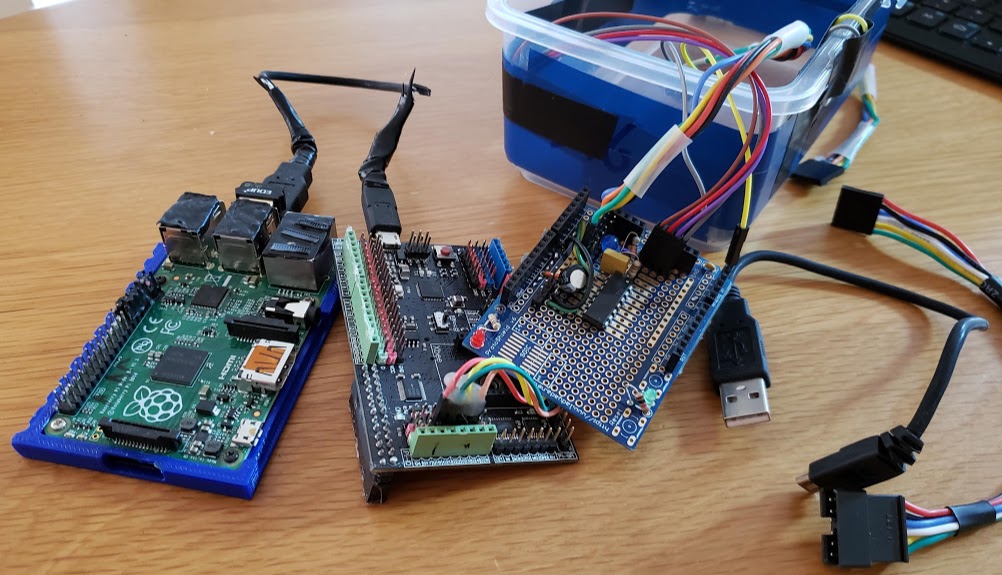
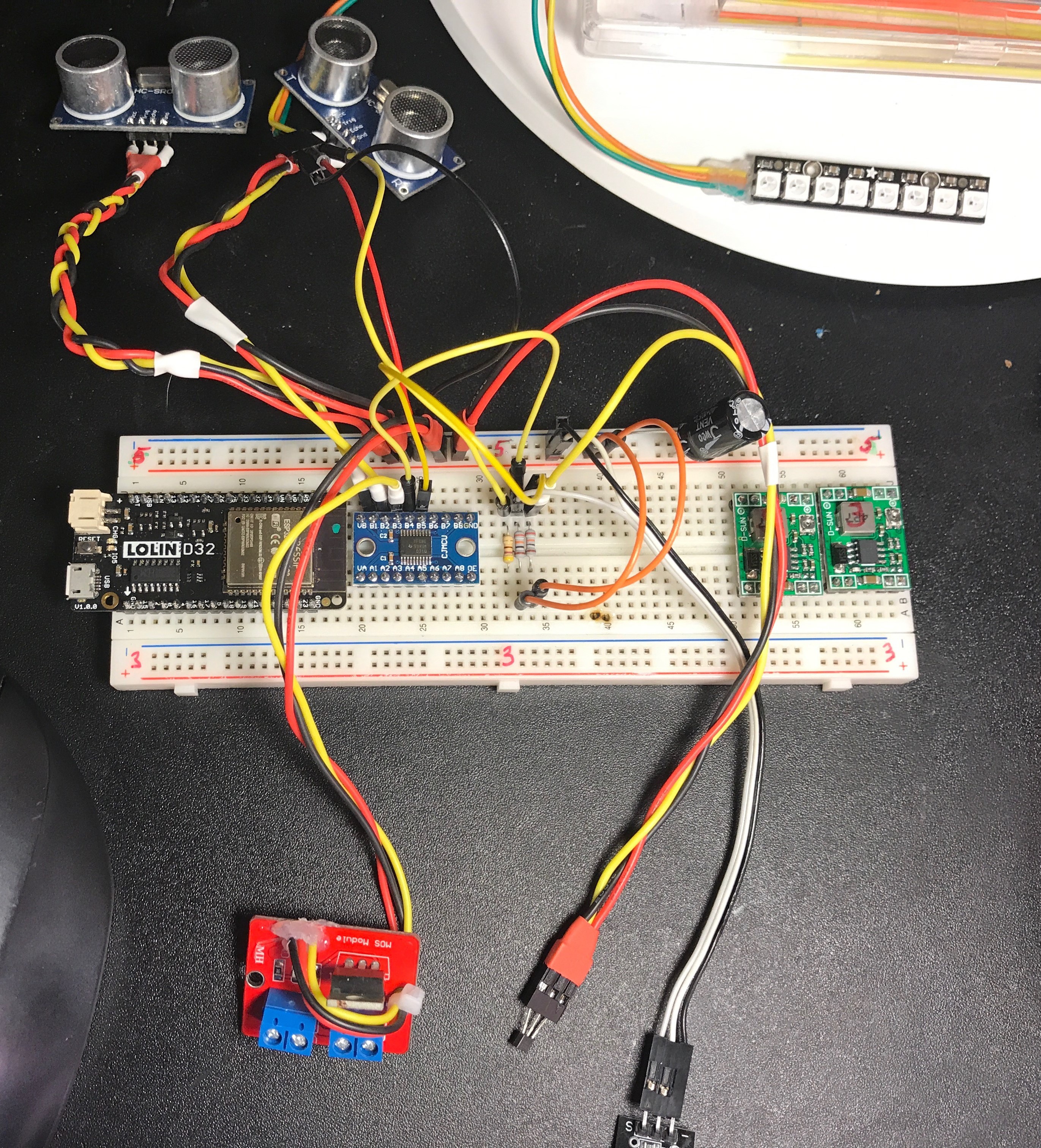
Moving towards a real PCB: the breadboard version of the JPods BaseBoard bogie controller.
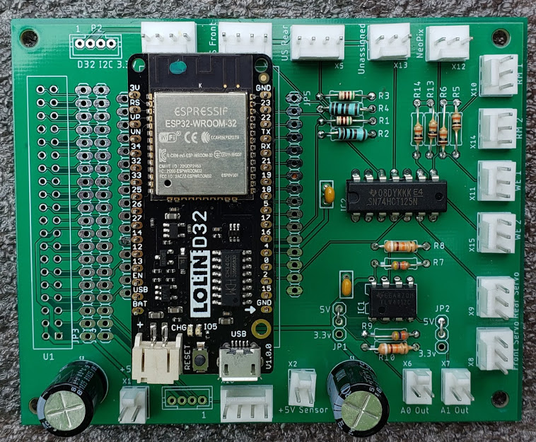
BaseBoard Rev 1.0
This is the populated version 1 (2019/2020) of the JPods "BaseBoard" designed by Bill James and Denny Fox. This PC board replaces the breadboard plus Arduino combination (seen above) used for early bogie prototypes. This board was designed to improve the reliability of the various input connections, to prevent misconnections, and to reduce the cluttered look of point-to-point wiring. The edge connectors used are 2,3, and 4 pin Molex type male headers using 2.00mm spacing (compare to the JST-PH connector family). The board could optionally be assembled with any other 2.00mm pin spacing connectors with a compatible footprint. The advantages of the Molex connectors are that they are both keyed and locking, and are also widely available. Additionally, there are two pads (one labeled "P2") for the Lolin D32 I2C bus that are 4 position, 2.00mm pin spacing. These pads can be populated with either JST-PH-M4 or Grove 4 pin PCB connectors to provide access to that I2C bus. Pay attention to the current requirements of any sensors placed on that 3.3V Vcc bus.
Note the unpopulated dual row of holes ("U1") to the left of the Lolin D32/ESP32 for the optional Raspberry Pi Zero mounted on its edge via a right-angle connector. There were several errors inthis board's design which required some minor modifications, which were manually done on this board and would be visible from the bottom side of the PCB. Also, some resistor values might need to be modified. This original board, as well as Rev 1.4, were designed using Eagle and manufactured by Seeed Studios in China. As it turns out, Rev 1.4, the "fixed version", also needs some modification to the board. This newer board is available as of June 2020. A ready way to distinguish the boards is to look in the top left corner. If connector "P2" is found there, it is the original board, as seen here. If the connector in that position is labeled "P3", it is the newer Rev 1.4 board.
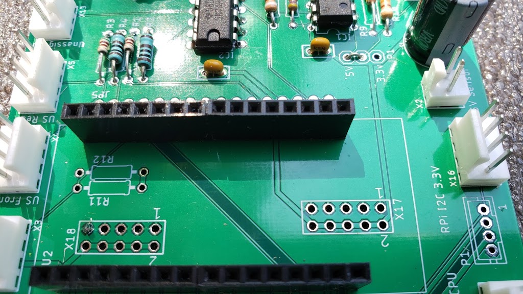
The socket for the ESP32 module consist of 4x8 IDE (0.1"/2.54mm) headers shown here. Unfortunately, joining the two 8 pin headers on each socket side, instead of using a single 16 pin header socket, leaves an excessive pin gap, requiring the header pins on the ESP32 module to be distorted in order to fit.
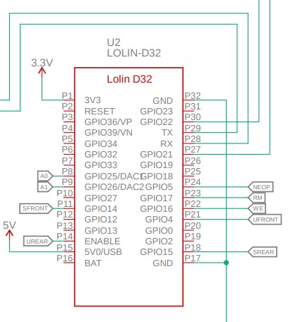
Detail of the D32 module on the Rev 1.0 schematic, showing the mislabeled ENABLE port.
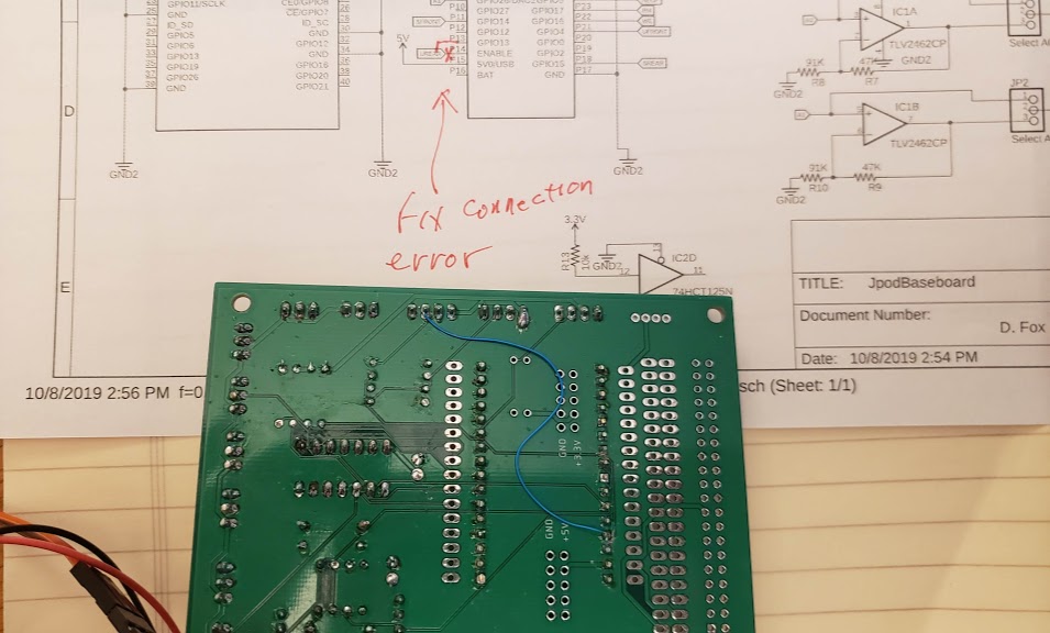
Another view showing part of the schematic annotated with repair notes, and the bottom of the Rev 1.0 board with a blue wire reconstructing the GPIO13/UREAR net after disconnecting it from the ENABLE pad.
BaseBoard Rev 1.4
The following photo shows the TOP view of the Rev 1.4 BaseBoard, highlighting the mis-routed trace from the D32 ENABLE pin (#P14, third from the bottom) to a VIA near the center of the board. The net name for this trace is UREAR, for "ultrasonic rear sensor". This UREAR trace should instead be routed from the D32's GPIO13 pin, located fourth from the bottom, or immediately *above* the ENABLE pin. This mis-routed trace continues from the VIA in the center of the board, to a trace on the bottom of the board which then goes to the left through-hole of R3 (also highlighted, near silkscreen label "JP5"). From there it goes straight up to pin #3 of X5 (UREAR connector labeled "US Rear"), and finishes its run downwards to the right side of resistor R4. Both of these last two traces are located on the top of the board and should be left intact.
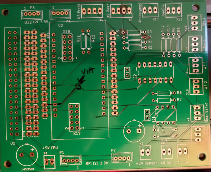
The repair for this version of the board is to cut the ENABLE trace just to the right of the square solder pad, before the trace turns northeast to the VIA.
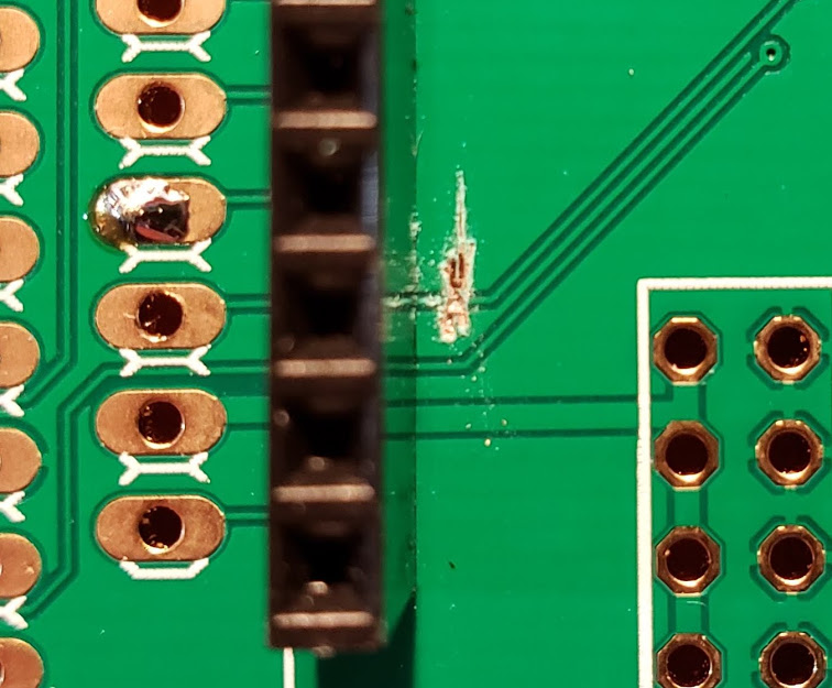
This shows the top of the board with the ENABLE trace cut. The copper trace is actually the lighter green stripe *between* the two darker stripes. This cut could have been much smaller/shorter, and here we see some of the surrounding copper ground fill exposed unnecessarily. Use a continuity meter (part of DMM function) to verify that there is no longer any continuity between the ENABLE pad and the left side of R3. The solder blob on the pad above the ENABLE pin is part of the second repair, detailed below.
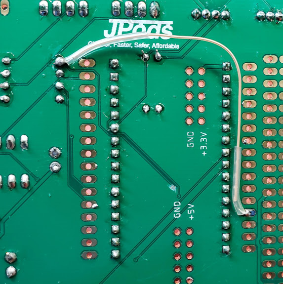
The second repair that must be made to the Rev 1.4 board is to attach that part of the circuit ("UREAR") removed from the ENABLE pin to the pad above it, the GPIO13 pin. The ideal repair would have a wire running directly from the existing VIA for that circuit to the GPIO13 pad, but I was not able to get an AWG30 solid wire into the VIA without risking a short/bridge to the surrounding ground fill. I opted to run a longer wire from the GPIO13 pin immediately above the ENABLE pin (lower right of photo) to the left side of resistor R3 (upper left of photo). Both points were easy to solder to reliably. To avoid interfering with the D32 socket header on the top side of the board, I ran this patch wire on the bottom side of the board, as seen below.
BaseBoard Rev 2021-05-31
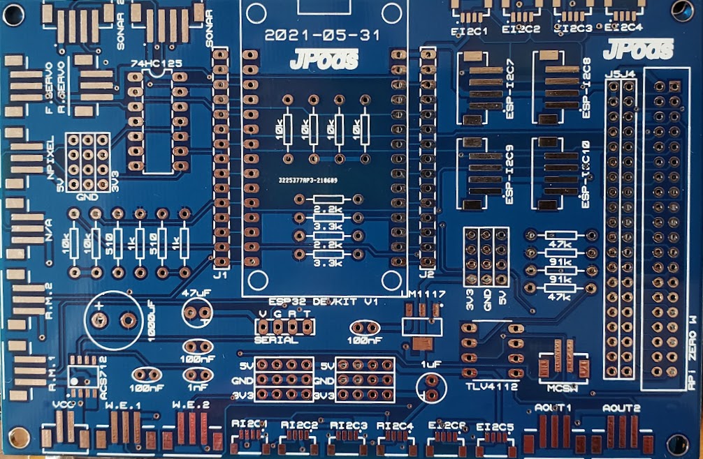
Version 2021-05-31 of the JPods BaseBoard controller, bare PCB. Note the mix of surface mount and through-hole components in this design. The goal was to put as much functionality on the board as possible while keeping it small. However, the intention all along has been to allow assembly and modifications by the typical maker, who might not have access to highly specialized tools such as reflow ovens.
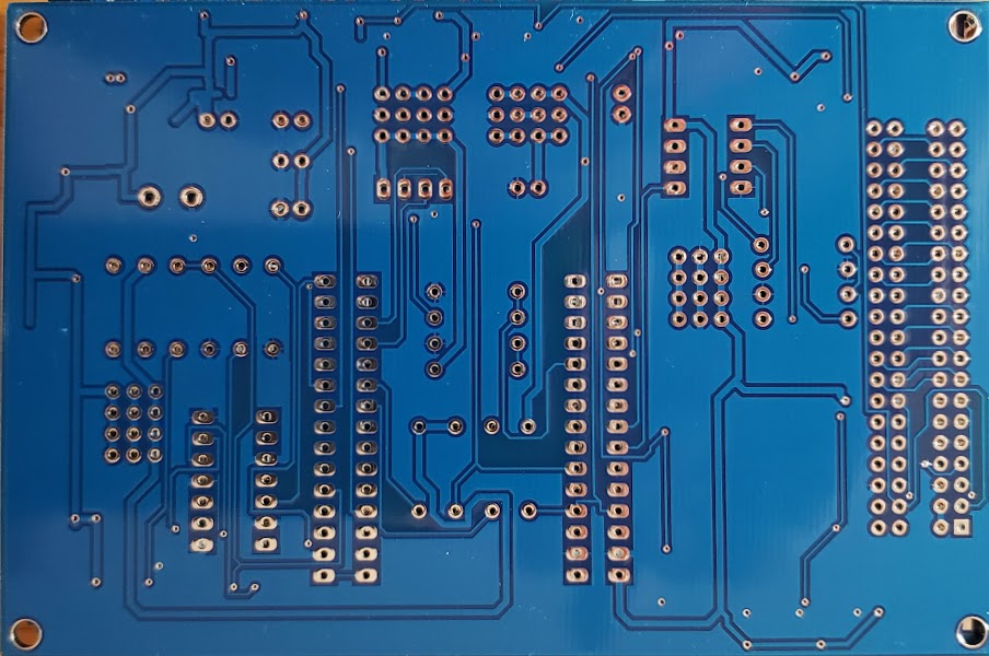
The back side of the board.
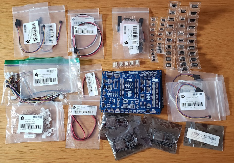
The bare board with assorted components used to populate the board.
Return to Top of Page
VESC Controllers (Vedder+ESC)
FlipSky is the manufacturer of the VESC6.6 Dual controller boards that we are using for driving the BLDC skateboard hubmotors in this project. The following photo shows the actual controller as delivered from the factory, with the supplied connector pinout sheet in the background. Some users just cut openings in the shrinkwrap to allow the necessary cable connections. While this adds physical protection to the board and its components, it also restricts the necessary cooling air flow over the parts and the solid aluminum heatsink the board is fastened to. There is thermal tape directly under the heat-producing MOSFETs to help cool them. Make sure that this heatsink is not trapped in dead air space.
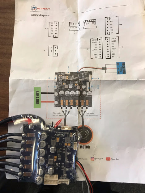
This is the "manual" from the Flipsky website. Follow this link for more information, including videos.
Return to Top of Page
Damaged Controller
This particular controller board was damaged in shipment. I removed the clear protective shrinkwrap to allow closer inspection of the board. After doing that, it became obvious that one phase wire filter (electrolytic) capacitor had separated from its solder pad connections and was simply rolling around on the board.
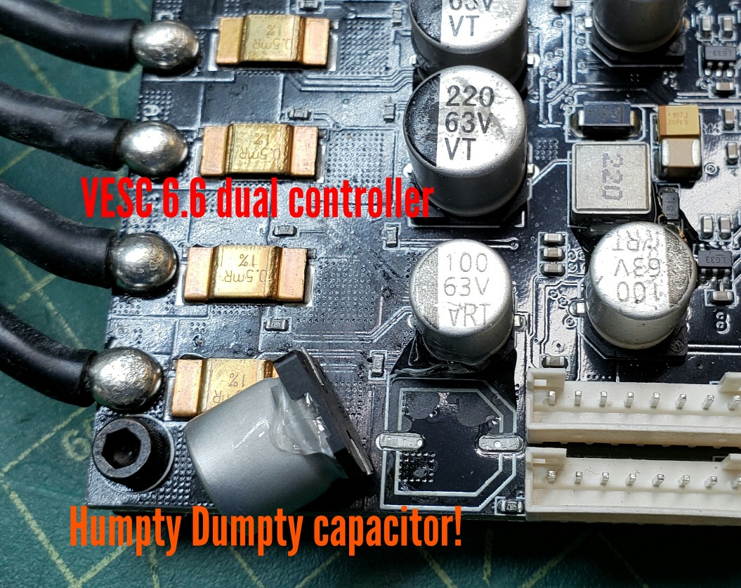
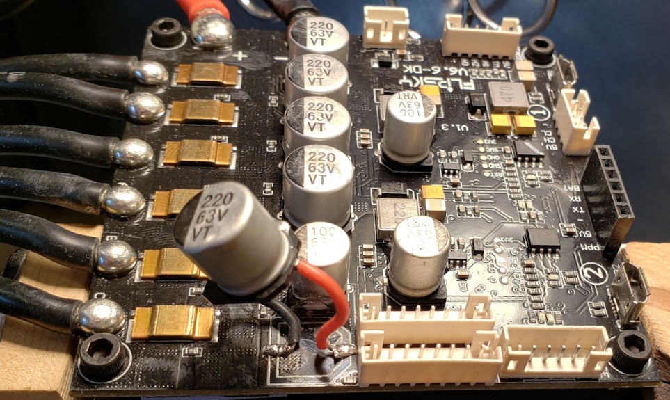
The presence of two plastic connector sockets right next to the positive terminal of the capacitor prevented me from getting heat to the pad for resoldering it. After consulting with an EE, it was determined that using short wires to reattach the cap was likely to work well enough. I used 26AWG silicone wire to make the repair:

Return to Top of Page
VESC (Dual) Controller Testbenches
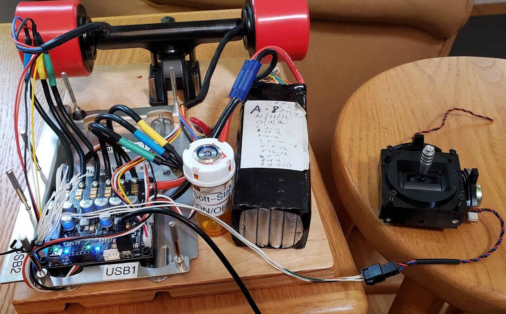
To make it easier to test and program the VESC series of controllers, I made two versions of small testbenches that included a jig to hold the controller, mounts for two separate motors, an onboard soft-start ON/OFF switch, and a 6S battery pack to provide portable power.
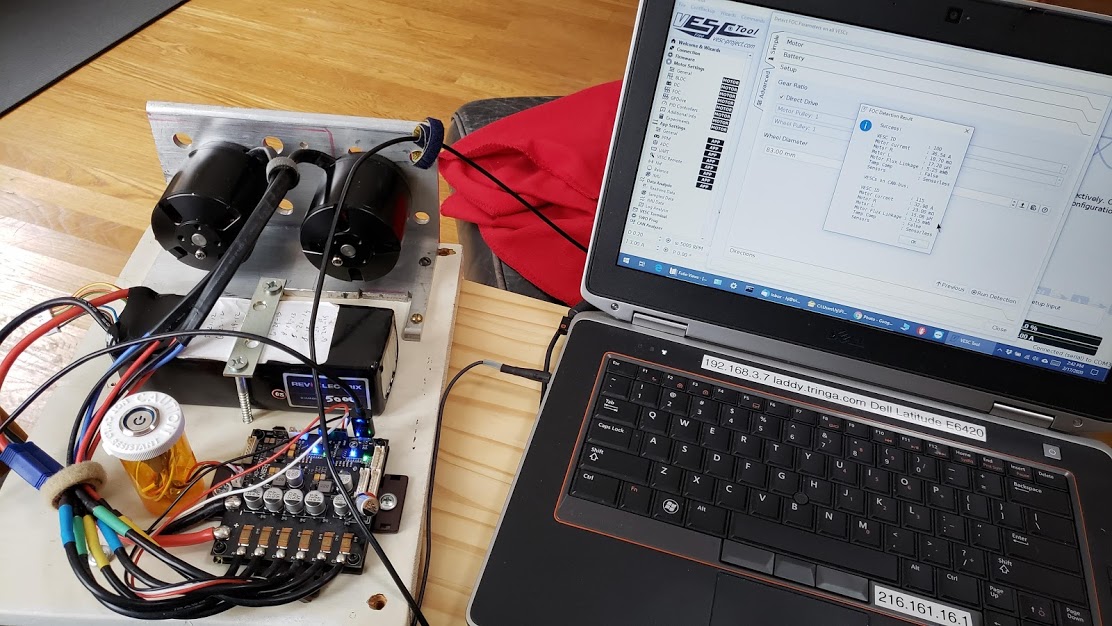
The following photo shows the testbench setup for programming and testing the VESC dual controller, with two generic black BLDC skateboard motors. Note the two blue "power" LEDs, and the two green activity LEDs (the left one only partially visible under the black USB cable), showing a properly functioning "dual" VESC. This was shortly after the repairs to the board were finished. The laptop screen shows the VESC-TOOL app open, with the successful results of having "detected" both of the BLDC motors and determining their electrical characteristics, including whether or not they use positional sensors, and any temperature sensors.
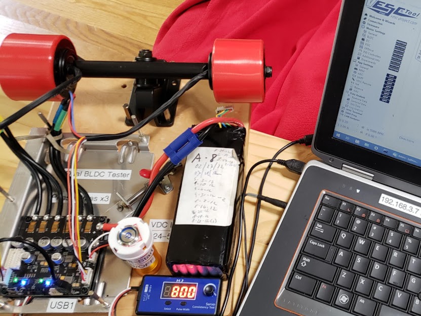
The next photo shows the testbench setup for programming and testing the VESC dual controllers, with two generic direct drive (in-wheel) BLDC skateboard motors. Note that these motors are using Hall sensors, but no temperature sensors. This required adapting the factory-supplied motor's 5 pin JST-PH-5F(emale) connector to properly mate with the JST-PH-6M(ale) connector on the controller.
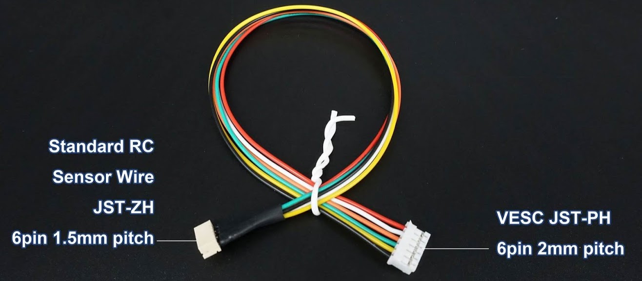
This shows the factory supplied adapter cable which doesn't solve our connection problem. While the 6 pin JST-PH-6F connector going to the controller board is correct, the 6 pin JST-ZH-6M connector does NOT mate with the five pin JST-PH-5F coming from the motor. Both the pin count (5 vs. 6) is incompatible, as well as the smaller "ZH" (1.5mm) pin spacing pattern, as opposed to the larger (2.0mm) spacing of the "PH" connector series. It can be made to work, however, by removing the JST-PH-6F housing from the adapter cable and swapping it out with the JST-PH-5F housing on the motor's sensor wire bundle.
Return to Top of Page
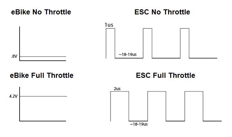
Typical motor controllers for ebikes and small electric vehicles are designed to connect to either a variable resistance, such as a 5-10K potentiometer ("pot"), or a Hall-effect throttle to vary the motor's speed and braking torque (if supported). In both of these cases the throttle signal is a simple DC voltage which ranges from about 0V for max regen braking, 0.85V for no throttle ("neutral"), to about 4.2V for full throttle ("floored"). Since this voltage change occurs with no pulses or steps("sampling"), it is described as being "analog".
Motor controllers for radio control ("RC") applications are known as "electronic speed controllers" (ESC) and are designed to connect to RC "receivers" which send the controller a 1/1,000 second (microsecond, "ms") long pulse for no throttle and a 2ms pulse for full throttle. Note that a "neutral" throttle position is 1.5ms pulse, or halfway between no throttle and full throttle. If configured this way, the motor/vehicle with a neutral throttle setting would be "coasting"; neither braking nor accelerating. This "Pulse Position Modulation" (PPM) signal is considered to be a "digital" signal. This shouldn't be confused with the similar "Pulse Width Modulation" (PWM) protocol which can also be used for motor control. The likely reason for using a digital protocol is that in the RC world the throttle signal is sent via radio waves (hence "radio|remote control", or RC), and that can be more easily done if the signal is already digitized. See the following diagram for a pictorial representation of the difference (courtesy of the internet).
Comparison of "ADC" (analog) and "PPM" (digital) throttle signals:
The consequence of this analog/digital difference in the throttle signals expected by the two different controller types is that using an analog throttle with a VESC requires an analog-to-digital ("ADC") conversion. For the VESC controllers we're using this "ADC" function is handled by the controller hardware itself, and is simply activated via a software setting. If this were not the case, a separate ADC device would need to be installed between the ebike throttle and the VESC controller.
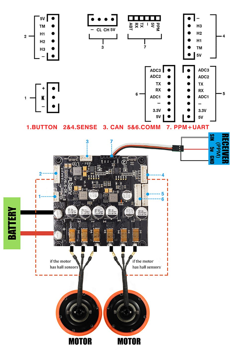
Also, the "dual" controllers which we are using are capable of controlling two motors via a single throttle. These VESC® 6.6 controllers have two identical connectors (#5 & #6) located at the edge of the circuit board. They are 8 pin JST-PH-8M, and each have three analog-to-digital ("ADC1-3") pins on them. Connecting a standard three-wire ebike throttle to 3.3V, GND, and ADC1 on one connector will control both motors, as long as the second motor/VESC is "slaved" to the first VESC via the CANBUS connection built into the dual controller(s). The controller's firmware settings must of course be properly configured using the VESC-TOOL to properly utilize the ADC throttle hardware. These settings include both selecting the correct options as well as calibrating the throttle's minimum and maximum voltages on the signal wire.
This model FlipSky VESC6 Dual controller comes from the factory with an approximately 10 inch long three-wire (red, black, and white) "Receiver" cable.
Go to the controller photo above, connector #7 labeled "PPM + UART", to see this Receiver/PPM wire and plug.
The three wires are terminated with a female IDC/duPont (0.1") connector to plug the VESC into a radio "receiver". The intended type of receiver utilizes the 2.4 GHz radio band transmissions from a remote throttle transmitter and translates them into a pulse position modulated ("PPM") signal the VESC uses to control the motor(s). Note that if you use certain receivers designed for the RC "hobby" world, their male pin sockets expect the controller IDC plug to have slightly beveled corners, preventing incorrect insertion. For skateboard use, these remote throttles are typically small hand-held units working on a single channel. The firmware on the controller must be properly configured for "PPM", as opposed to "ADC", input.
Do NOT be tempted to connect any kind of potentiometer or ebike type analog throttle to this three wire PPM plug! As they say, "Don't ask me how I know this". While the smoke that comes out doesn't smell as bad a burning electrolytic capacitor, it is still smoke.
Note that these three wires are simply soldered on the underside of the board to their corresponding header socket pins (black=negative, red=5VDC positive, white=PPM signal), and are extremely prone to being broken off. It may be a better idea to utilize a custom made cable that plugs into the standard 0.1"/IDE header on the top of the board. To use an ADC (analog) throttle, we'd connect it to one of the ADC sockets on the controller via a JST-PH-8F plug, populating just those positions we'd need, such as ADC1 for the signal, 3.3V positive for Vcc, and the negative/ground/common wire.
Return to Top of Page
Below we see the controller testbench shown with a stock dual-axis "joystick", harvested from an old, non-functioning RC 'hobby' airplane transceiver. Only the "throttle" axis is being used here, connected via an inline JST-SM three conductor plug pair. Two wires are for the +3.3VDC and Ground, while the third is the throttle 'signal' wire. The source current is supplied by the controller. Note that the input voltage in this case is 3.3 volts, but in the typical ebike world this would be 5 volts, but it's really up to the controller to determine this.
To use this type of throttle, the VESC dual controller is programmed to accept a single analog ("ADC") input , since this joystick is the functional equivalent of a 5K pot configured as a voltage divider. However, if we use the *other* axis on this joystick (typically mapped to control the ailerons of an airplane), we get a voltage divider with a center detent (neutral') position. This allows us to map a single throttle control to provide both positive and negative going signals. This provides the additional functionality of having the bogie being able to go forwards and backwards, or using regenerative proportional braking, all with a single control input. This capability is made possible by the firmware built into the VESC controller.
Return to Top of Page
VESC Controller Failures
Red LED flashing 3x pattern & FAULT_CODE_DRV
This condition arose while using a FlipSky VESC 6.6 controller with two generic BLDC skateboard motors. Using the VESC TOOL app (revised replacement for "BLDC-Tool") on a Win PC laptop, the app and controller successfully did an autotune ("detect") of both motors. Both sections of the VESC dual controller had steady blue and green LEDs lit, with no red LED activity. The green LED would flicker when data was being transferred to or from the controller.
VESC TOOL screen showing successful "detection" of motors
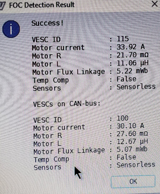
After attempting some more software configuration to use a 5K pot (basic ebike resistance throttle) as a throttle, both sections of the dual controller began to display flashing red LED's in a pattern of three flashes ON, followed by a slight pause (OFF state). The VESC TOOL debugging console then also showed the FAULT_CODE_DRV error code.
I started doing some research here to figure out what the red LED 3x blink pattern and FAULT_CODE_DRV error code in the Debug window of the VESC TOOL means.
It's obvious that this error condition goes back to at least 2015 and affects all variants of the VESC hardware, whether they are DIY, manufactured by founder
Benjamin Vedder, or manufactured by third parties such as the VESC here, made by FlipSky of China.
Unfortunately this combination of red LED flashing 3x combined with a FAULT_CODE_DRV error in the app's terminal output is not uncommon, and can be caused by
a wide variety of issues. On the simple side, some have reported this error condition after just failing to enter the correct battery voltage value into the app during configuration of the VESC. Some have had the error condition occur apparently 'out of the blue', and have not gotten any answers after posting online.
See this post at vesc-project.com for an example in which the poster said "The fault only happens when using the remote but then goes away." This 2018 post had not yet received any response by 2020. Frequently posters get a response that their (often brand new) VESCs are now "expensive paperweights", even though that's probably not true in many of these cases. Sometimes one respondent to a post tells the poster his VESC is "bricked", while the next poster asks one more question, and based on the original poster's reply provides a simple solution to the problem.
Even though this brand new VESC was damaged in shipment, it clearly worked *once* (after the obvious repair of the broken-off capacitor) to detect two motors while on the testbench. These motors were unloaded (no resistance on the shafts), not hot, and run on 6S/24 volts, which is in the middle of the voltage range acceptable to the VESC's components.
There was no magic smoke or visible signs of component damage, so at this stage a software glitch is still the likely suspect. Vedder, the projects founder, does say that the DRV8302 MOSFET driver chip used in this design is not very robust, so a failed chip remains a possibility. I don't think this is so, however, because for a brief time the #2 side of the dual VESC board booted without the blinking red LED, after I did a number of 'resets' to default conditions and reloaded the firmware using the VESC Tools app.
Debugging VESC Failures
One method for spotting a VESC failure is observing the three LEDs on each single VESC. If a red LED flashes after the VESC finishes booting, an error condition is likely. Another method involves querying the firmware loaded onto each VESC's main logic chip, an STM 32 microprocessor. It will answer queries sent to it by the VESC Tool app. In the Terminal window, sending the command "fault" or "faults" will return the text versions of the error code(s). If for some reason it's no longer possible to boot the VESC, it may be necessary to intall a new bootloader using the STM32 ST-LINK utility and programming tool.
See also this post at vesc-project.com for another example of the same issues we're having here. The pattern is that everything was working fine during bench testing, but then the dreaded red LED 3x flashing appears, along with the FAULT_CODE_DRV error code in the terminal window of the app. In this example the poster's problem also mirrors ours in that the detection process measures the motors' milliHenry induction (L) ok, but fails to measure the resistance (R). Problems typically appear in FOC (field oriented control) mode, and some users have said that they could get it to work in BLDC mode while it was continuing to fail in FOC.
The posted "solution" to this problem was the common suggestion to replace the MOSFET driver chip:
The more time one spends looking for answers to this VESC error issue, the more obvious it becomes that "it's a thing". The following link points to another example of the same type of error, this time with the same model VESC as we are testing here.
forum.esk8.news/t/flipsky-fsesc-6-6-dual-plus-issues/11119 October 2019
As a test I'd suggest you lower the battery amps to 30 and see if there errors still occur. Lots of these errors are phantoms using earlier VESC further revisions on FlipSky & Maytech VESCs.
If the errors still occur try loading the Ackmaniac firmware and see if it still happens.
...
In my experience with the FlipSky 4.20s anything over 50a is gonna cause problems. I haven't used the 6s so cannot do other than theorize.
Possible FAULT_CODE_* error messages generated by VESC-TOOL: [vesc_tool/datatypes.h]
Return to Top of Page
This is the revised open source replacement for the "BLDC-Tool" app designed to program the VESC hardware controllers developed by Swedish Benjamin Vedder. A big THANK YOU to Benjamin, since he has been working on this project as a labor of love. The VESC-TOOL will read and write the configurable parameters of the VESC's onboard 32 bit microcontroller/logic/CPU chip, as well as allowing the uploading of new firmware to the VESC hardware. It also is a GUI tool to manage all of the parameters, and allow configurations to be backed up to external files using the standard XML format for storing the settings. The logic chip on the VESC board has an internal bootloader which allows the VESC Tool to connect to it via a USB cable. Without a functioning bootloader, the VESC logic chip must be programmed using a separate external tool designed for the purpose, such as the STM32 ST-LINK utility and programming tool. The dual VESCs from FlipSky that we're using all come with a working bootloader (so far!).
Downloading the 'free' version of this open-source software entails going to the https://vesc-project.com/ website and picking your way through a series of counterintuitive and obtuse steps involving the creation of an "account", filling a "shopping cart", obtaining a code, optionally printing an "invoice", and finally (at least in my case) struggling to find the actual DOWNLOAD LINK for the software. Maybe there's something lost in the translation. When a new version of the software becomes available, it's rinse and repeat (except for the new account creation). After some googling (and finding that I'm not the only one unable to find "the download link") I discovered that the secret is to CHECK YOUR EMAIL! The appropriate links for the different OS versions of the VESC-TOOL are there for you to use. One of the emails sent to your address will contain a link to a zip file, which when unzipped will yield the VESC-TOOL executable -- which is the only file in the zip container. Once that's done, things return to normal and you simply run the app and follow its prompts.
[Note: There may be another direct download option via links on github. I didn't explore that route - yet.]
If you want to watch a youtube video that covers this entire process very well, watch this one: https://www.youtube.com/watch?v=CMTnVz6FVq4 I'd actually give it a "like" if it didn't have the obnoxiously annoying background 'music'. Even with that, the voice-over is understandable and informative.
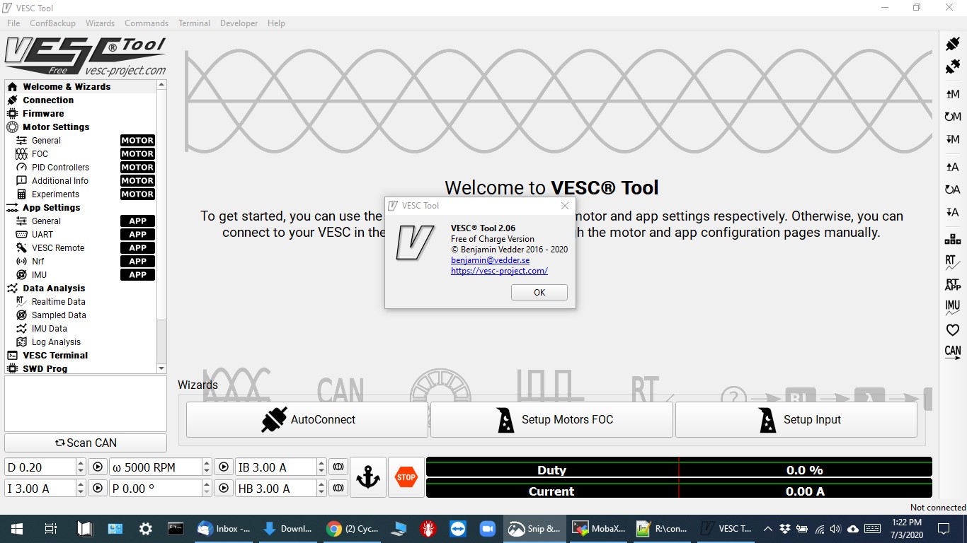
Photo of the app's main screen, running on a Windows 10 OS. The small popup window shows that this version has been updated from the 2.02 version to 2.06 (done July 3, 2020).
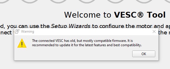
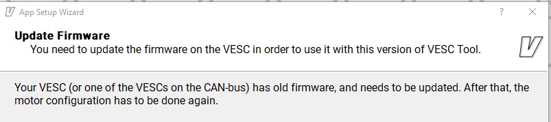
This popup window, encountered when connecting a VESC® controller, suggests updating the firmware on the VESC hardware. Since the VESC-TOOL software will likely be updated more often than the VESC hardware connected, this popup is likely to be seen every time a new version of the app is installed and used to program a VESC. Upgrading the hardware's existing firmware is entirely optional, unless...
...it's not! Here we're using the tool's SETUP wizard to modify the settings for a dual VESC controller programmed with an earlier (2.02) version of the VESC-TOOL.
Return to Top of Page
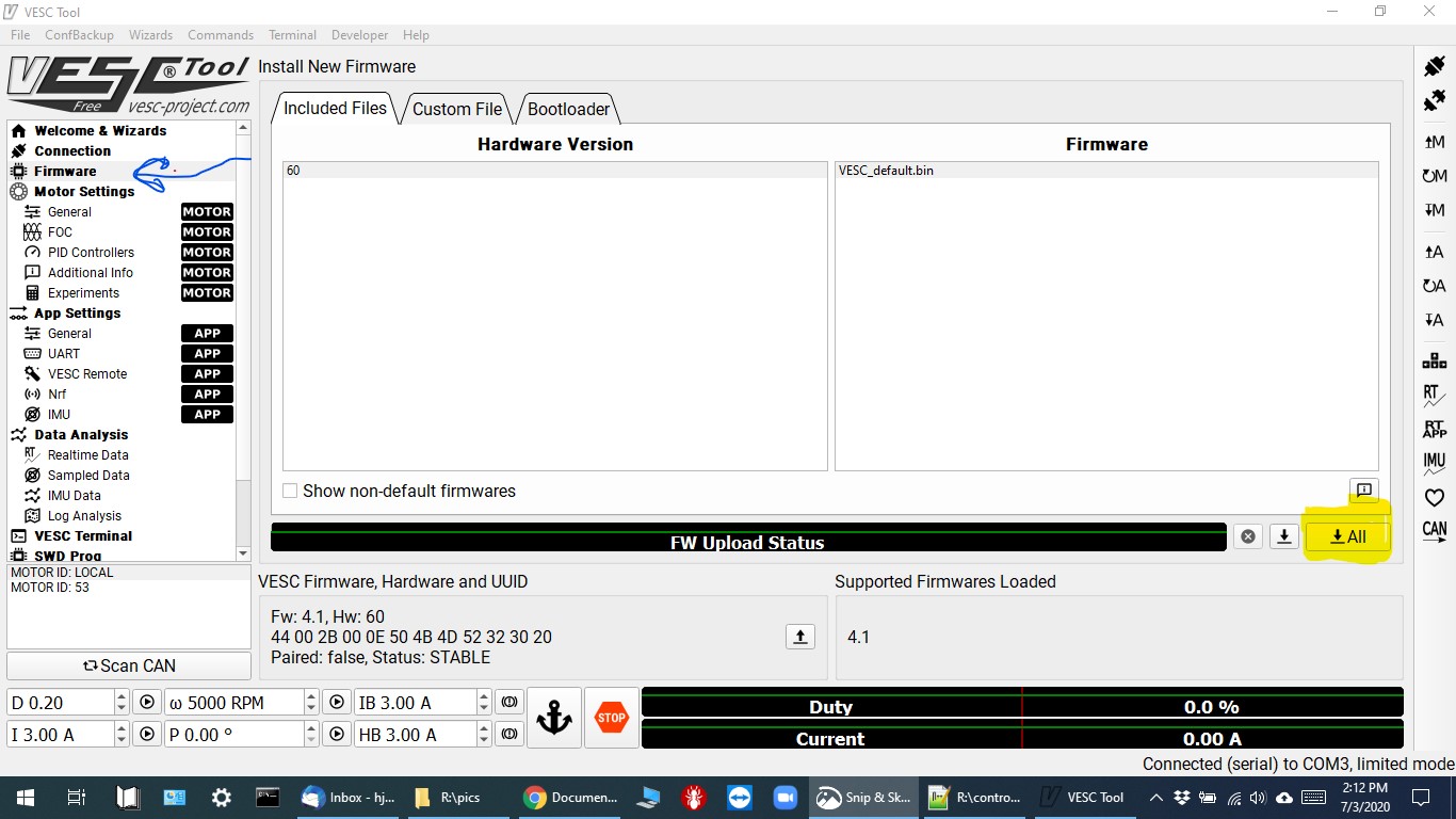
After selecting the "Firmware" option on the left-side menu (hand-drawn blue arrow), we see this screen. It shows that the currently loaded firmware is version 4.1, which was installed using a previous version of the VESC-TOOL. We will be updating both halves of the dual controller at the same time, so we'll select the "All" button (hand-drawn yellow hi-liter). Both green LEDs on the dual controller should be blinking rapidly during uploading/writing process.
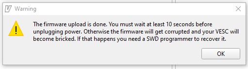
After a successful write, the following popup warns you to wait 10 seconds before powering down the controller. Note that the controller has been automatically "disconnected" from the VESC-TOOL software after the firmware update process, and the upload progress bar will say "Upload Done". After this step, I would recommend leaving the controller connected to the computer via the USB cable, but powering it down for at least a few seconds, and then powering it back up -- basically "rebooting" the controller to confirm that the new firmware is working. Select the "Connection" menu item from the left side of the screen, and reconnect the controller to the VESC-TOOL app by clicking on the "Autoconnect wizard" bar located near the bottom of the screen.
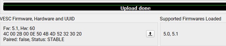
Go back to the Firmware screen using that menu option and verify that the loaded firmware is now a newer (higher) version number. The following screen snippet shows that the same generation of controller hardware ("Hw: 60") has now been upgraded from version 4.1 to version 5.1. Apparently the "hardware" (referring to the controller itself) version of "60" correlates to the "6.6" version of the VESC.
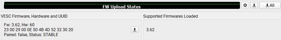
This screen portion shows a fairly recently purchased VESC 6.6, using hardware version "60", that was shipped with firmware version "3.62". When first connected to the VESC-TOOL app, it causes the app to display a popup screen (see above) that says that the firmware is old but largely compatible with the current feature set. It's considered to be good practice to update the controller's firmware to the most recent version available in the updated VESC-TOOL app that you are using. This controller was also upgraded to version 5.1, after this screenshot was taken.
[todo: Add motor detection screens!]
Note: remember to write motor configuration updates to controller -- icon menu, right side of screen
To make sure that the detection process doesn't overpower the motor, select the proper size of the motor being detected. Most 'skateboard' motors will fall into the "Medium Outrunner - 750 gram" category.

Return to Top of Page
After getting a new controller or completing any new firmware upload to an existing controller, its input parameters need to (re)matched to the input hardware -- typically a "throttle" -- being used with that controller. To do this, the controller must be connected to the VESC-TOOL app, as well as whatever input device will be used. The motors (assuming a dual controller) to be controlled should also be attached in order to fully test the new configuration.
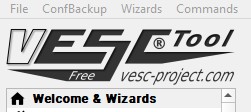
To enter the Input Setup screen, select the "Welcome & Wizards" menu item located in the top left of the main screen. From the Wizards screen, select the "Input Setup" wizard button, and follow the intermediate 'help' screens. These intermediate screens include the app scanning the controller to find what it thinks is attached, and how they are configured. When you are configuring a VESC® dual controller, one (the 'master') will typically be found to be connected via the USB port while the other is connected via the CANBUS. It doesn't typically matter which is which, as long both are recognized. For our dual-drive skateboard setups, both controllers should be responding to the same input device.
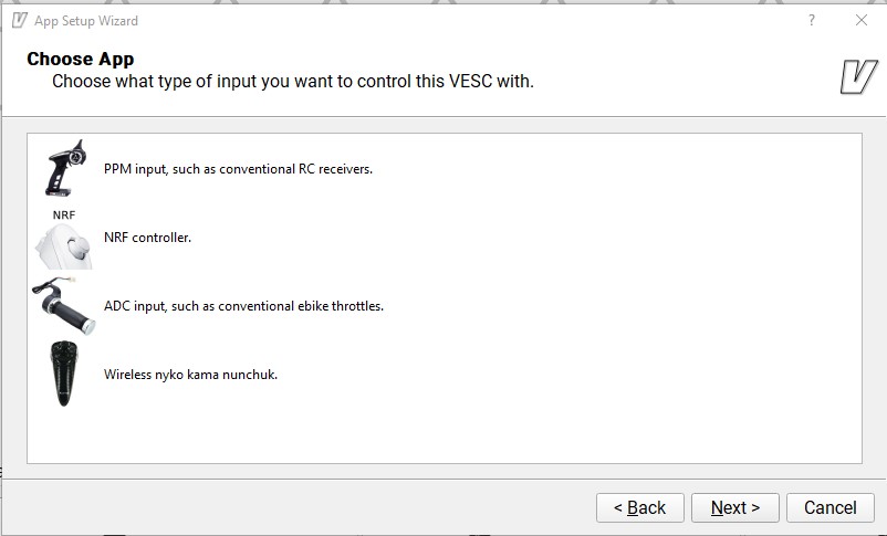
Eventually you will get to this following critical screen, which allows you to select which type of input you will be using to control the motors. During the initial testing and configuration that I did with these controllers and motors, I used a basic 5K potentiometer to simulate a simple analog throttle, similar to those used in the ebike world. For a more complex application, I also used a salvaged joystick control from an old hobby radio controller. This dual axis control employed self-centering pots, each of which allowed a single throttle to control both acceleration and ebraking if so configured in this Input Setup part of the VESC-TOOL. Selecting the "ADC" option from this popup menu screen enables the use of virtually any device which is capable of accepting an either 3.3 or 5 volt source provided by the controller, and 'dividing' that voltage into a value proportional to the amount of 'throttle' applied by the user.
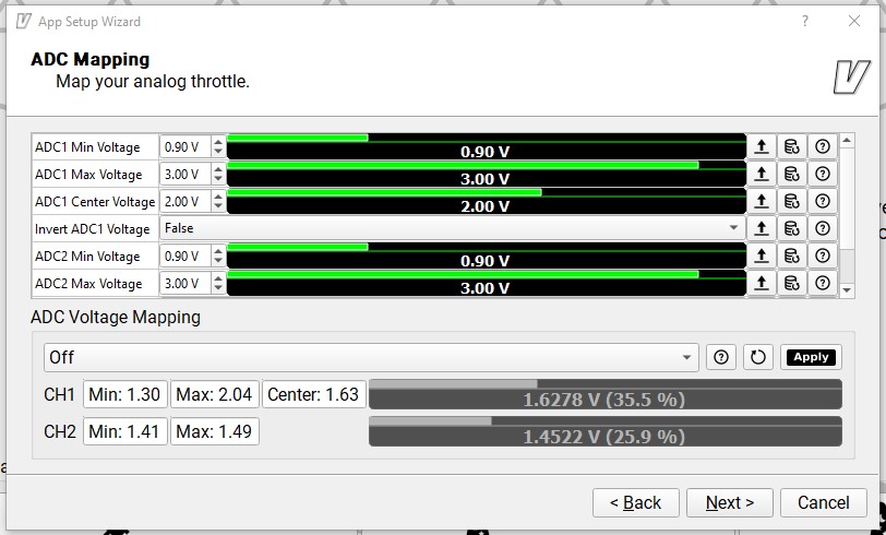
As soon as the user selects the "ADC input ..." option, the following screen pops up. It is the first "live" screen which shows, in realtime, whether an input device is detected, and where it currently is set. Moving your input device's controls at this screen should be immediately reflected by changed values appearing in the CH1 or CH2 (or both) status bars. Assuming your analog input device is connected on the controller's ADC1 pin, the variable output will appear on CH1, as on the following screen. In this example, I've connected a 5K joystick device which shows a "center" (resting) value of 1.6728 volts (rounded to 1.63 volts). Since this value should be 1/2 of the 3.3 nominal input volts, its being half of 3.3456 volts is actually pretty close to perfect. If the input voltage were exactly 3.3 volts, half of it would be 1.65 volts, which we could arbitrarily select as the "ADC1 Center Voltage", and proceed with testing that value. Once you feel confident that your input device is being properly read by the VESC-TOOL, you "map" your input device values with the values the controller uses to control the motors. If your input device is producting reasonable values, select a throttle control method from the dropdown box labeled "Off" by default and then click the "Apply" button to save your choices in the app. Click the Next button to proceed to the next step in the ADC input configuration process.
The ADC Configuration screen allows the controller to be configured to behave in a manner desired by the user. Remember to write the settings to the controller when all selections have been made. In version 2.06, at least, the only confirmation you get when writing these settings to the controller are very brief blinks of the green 'data' LEDs.
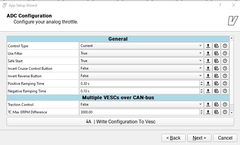
Continuing with this same example, here are some of the configuration choices made:
Current Reverse Center
Current control. The output is off when the input is centered. Input less than center brakes until the motor stops, at which point it it starts in the reverse direction.
Done!
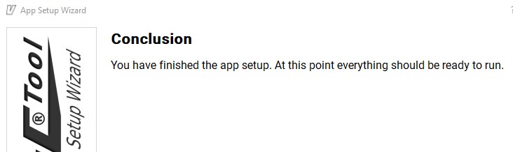
... and it works. Push lever forward to make bogie go forward; pull back to make it go backwards; let go to make it stop. It's a good idea to power everything down, and then back up, and safely test all features after rebooting -- making sure the wheels are spinning freely in the air during this entire process. You have been warned.
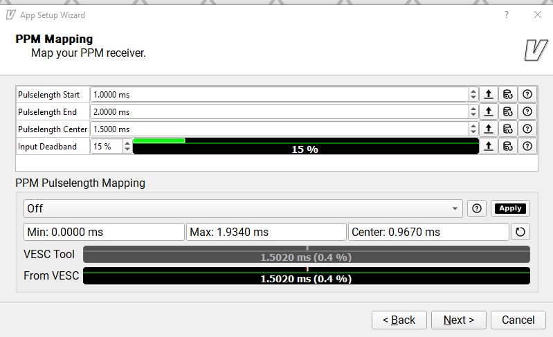
If you plan on using a 2.4GHz radio system such as those used in hobby "RC" (think model airplanes, etc.) applications, the same INPUT SETUP Wizard can be used to configure your VESC controller. By simply selecting the PPM choice when running the wizard, you'll be presented with the choices relevant to this method of throttle control. For this example I used a Spektrum DX6i transmitter coupled with an AR6200 6 channel receiver, also made by Spektrum. The receiver is connected to, and conveniently powered (5VDC) by the VESC controller via a standard three-wire servo cable. Note that the typical servo cable plugs, while mostly the same as the common 2.54" header ("duPont") plugs, have two of their corners slightly chamfered to fit into the receiver's sockets.
Using this 6-channel combination is largely overkill, since driving the bogies via the VESC controllers really only requires the single throttle "channel". However, such features as e-braking, reverse motion, as well as other functions may be desired for the skateboard bogies, and these multi-channel radio tools could enable those features. Ultimately, of course, all control methods and the associated channels used for the skateboard bogies operating in the network will be based on dedicated microcontrollers running custom firmware. The radios used could utilize any number of frequencies and protocols, including wi-fi, bluetooth, nRF, or - as in the following example - 2.4GHz.
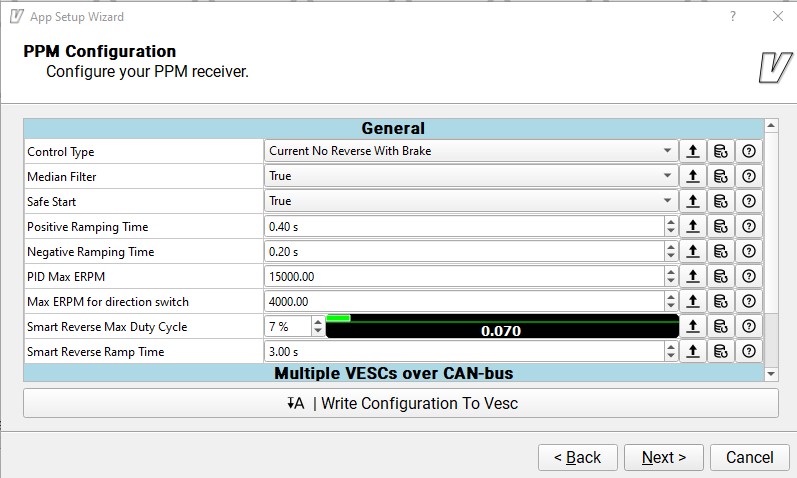
The following screen shows the default values in the basic PPM properties that can be configured. Again, the throttle lever on the radio transmitter must be "mapped" to the controller's expectations. Even though the screen talks about mapping the throttle to the *receiver* (which the part of the radio system mounted to the bogie), the throttle is really on the *transmitter*, which is NOT on the bogie. The receiver simply collects the signal, decodes it, and passes it on the PPM input on the VESC controller board.
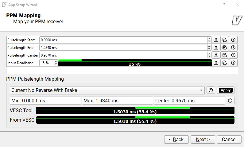
Note that in the following screen that the "Current No Reverse with Brake" option has been selected from the PPM Pulselength Mapping dropdown box, and that the green colored bars reflect the "live" movements of the throttle control on the transmitter. Read the very useful built-in help screens in the VESC-TOOL app to find out more about the available options.
Return to Top of Page
Android Phone app Tool
This free software app by FlipSky, is available only for Android OS devices for now (in the middle of 2020). It can be used both to program certain firmware parameters on the VESC® controllers, as well as to display certain realtime data sent from the controller.
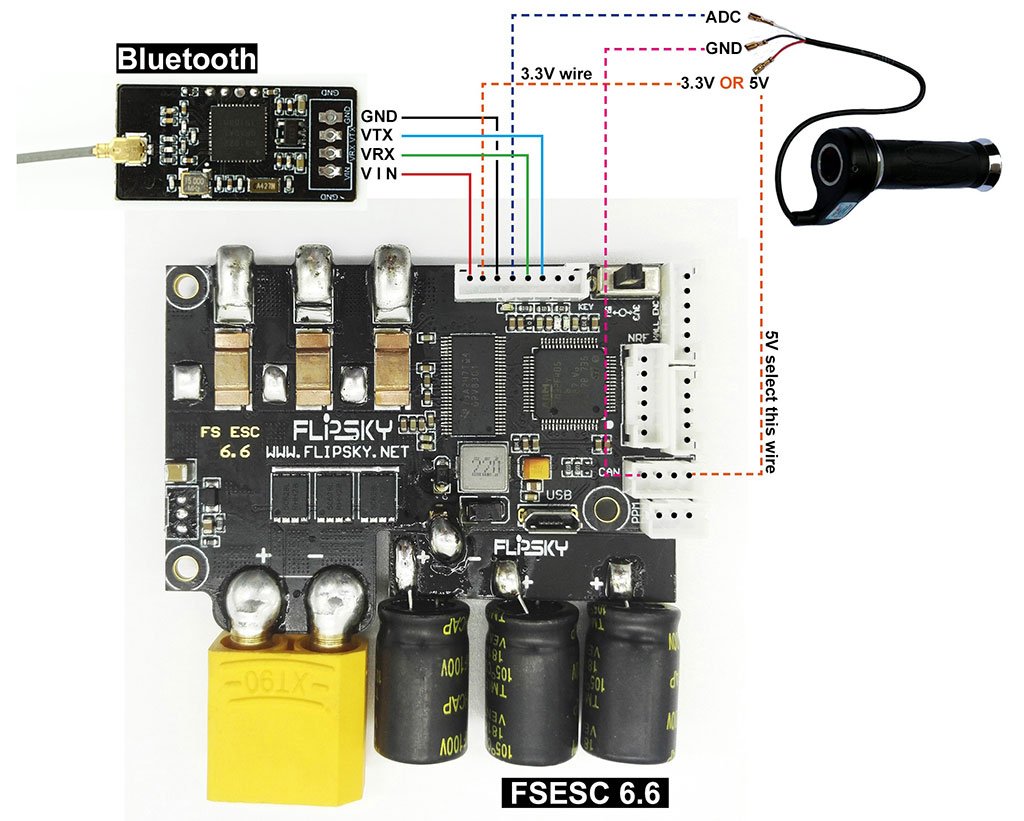
In addition to the freely downloadable phone app, it requires a Bluetooth module sold by Flipsky for around $10 US. The Bluetooth module is powered by the controller and plugs into the onboard JST-PH-8M "Comm" port, which is also used for connecting analog (ADC) throttles and sensors.
The following shows a functional diagram of how to connect both the Bluetooth module and an ebike type ADC analog throttle to a VESC controller. Apparently all of the Ground connections on these controllers are common, since this official FlipSky diagram shows that either the 3.3 or the 5 volt rails can share the same Ground. Refer to the VESC® manual above for the exact pin assignments on the dual Comm ports (connectors #5 and #6 in the manual). On the Dual controllers we use that are constantly connected via an onboard CANBUS link, either COMM port may be used.
VESC programming tips
Return to Top of Page
Controller Repair
A typical failure enountered in BLDC motor controllers is a "blown MOSFET". A MOSFET commonly fails in either a "short" or an "open" condition, and either failure mode can be diagnosed without taking the controller apart. If you have access to a cheap "ebike tester", you can use that to do the diagnosis. If not, use any available digital multimeter (DMM) and follow the procedure below.
Set the DMM to resistance (Ohms) mode and test between the battery power inputs (red and black wires) to the controller and each of the three phase wires (blue, yellow, green). Controllers will have an even number of power MOSFETs, one or more for the "high" (positive) power rail, and one or more for the "low" (negative) rail. Regardless of the number of pairs of MOSFETs used in the controller, this test will require six resistance readings. With one probe on the negative battery input (black wire), test for continuity with each of the three phase wires in turn. Repeat this series with one probe on the positive (red wire).
For functioning MOSFETs, expect a resistance around 5K ohms when testing the low side rail, and an increasing set of resistance values on the high side rail, due to the presence of smoothing capacitors being charged in the circuit. If the resistance is zero (or close to it) for any connection, a MOSFET is suffering from a dead short. If the resistance is infinity (or close to it) a MOSFET has failed in the open mode. Another clue for a shorted MOSFET is that when the motor is still in the vehicle and connected to the controller there will be a more pronounced cogging effect. This is the same result you get when you short the motor's phase wires together (any two, or all three).
Watch Grin's youtube video for more details, including how to make the actual repair. The video covers a Grinfineon controller, although the technique used will work with many other controllers.
Return to Top of Page
Controller Resources
Google is your friend (some of the time).
Return to Top of Page
Return to Top of Page
Return to Main Menu