This page's link: "http://erowbike.com/eskybike"
Return to Main Menu
SkyBike Versions
-
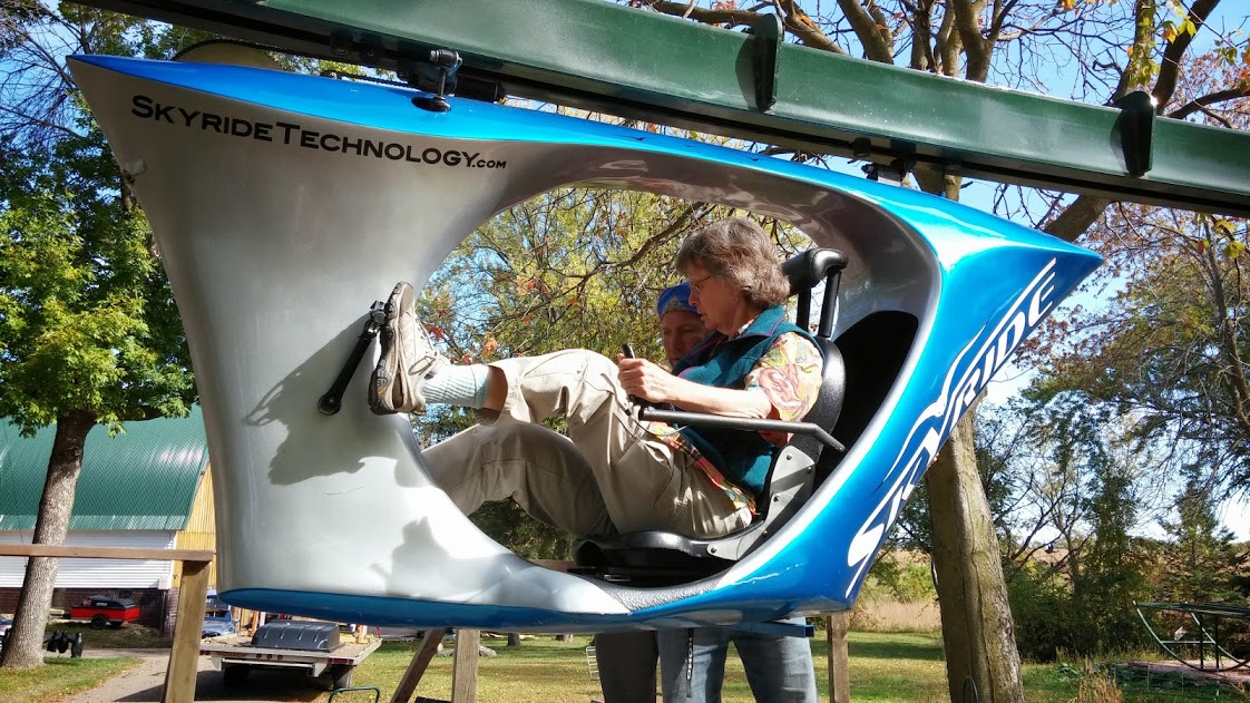
SkyRide: The production SkyBike with a totally mechanical drive -- no e-assist. This is the version originally designed and installed on the Carnival Cruise ships, ca. 2017. Watch them in action in
this youtube video. Note also that this is a "closed frame", without the unobstructed view of the newly proposed "C-frame" version.
-
This shows a pre-production version of the SkyBike on the 6" outdoor track at the farm (Waconia). This version is still an all-mechanical, direct drive version. [Oct 7, 2013]
-
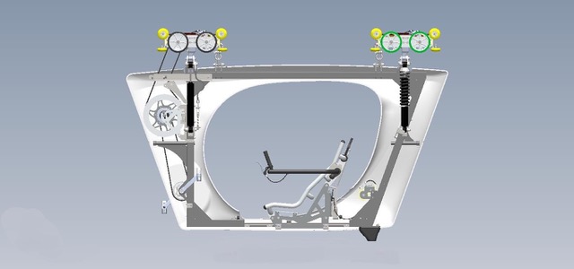
This is the prototype version of the 'closed frame' (not "C-frame") SkyBike. This version was the testbed for the e-assist and fly-by-wire functionality. The 6x6" outdoor test track at Waconia is visible in the outdoor background. Not shown on the frame are the seat, cockpit, batteries, resistance unit, and the in-track drive bogies.
-
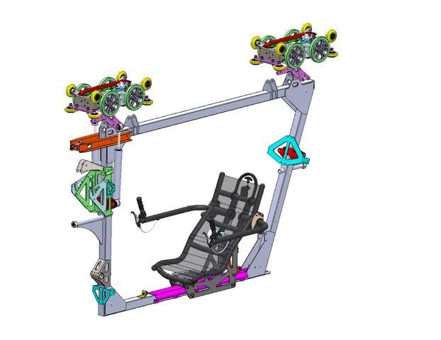
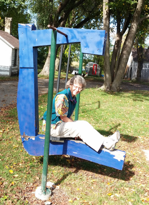
Early on(pre-2013), Scott Olson had already been enamored with the "open plan" architecture for the SkyRide vehicles. The great views and feeling of freedom in this "C-frame" stationary model are aptly demonstrated by this human rider here. Now to make the next 'lean-and-mean' prototype that actually will move on the track!
eSkyBike "C" Bike Frame
The "C" platform of the ceSkyRide vehicle will (at least during development) simply be a carrier for a 'recumbent' style bike frame. This will simplify the mounting of a seat, cockpit for the controls, and a pedal/bottom bracket assembly necessary to provide the resistance unit.
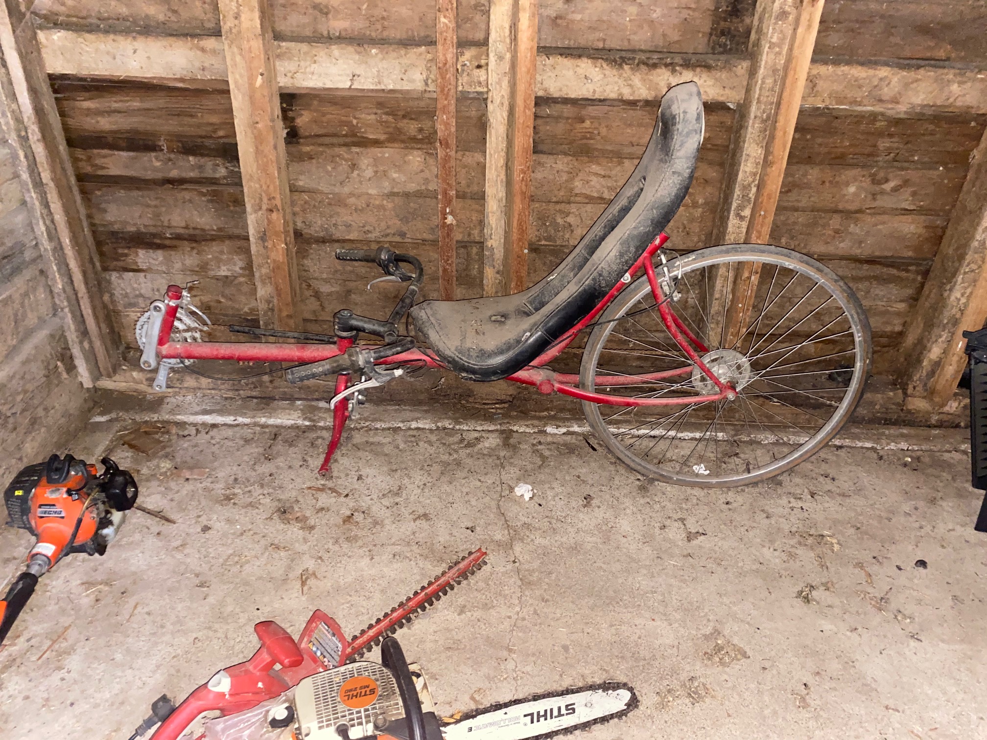
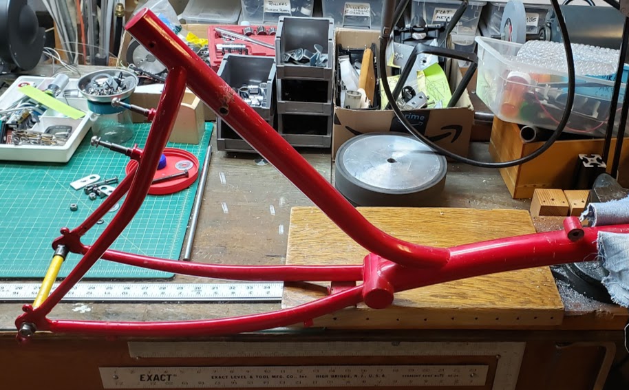
Red recumbent frame
From humble beginnings, out "at the farm":
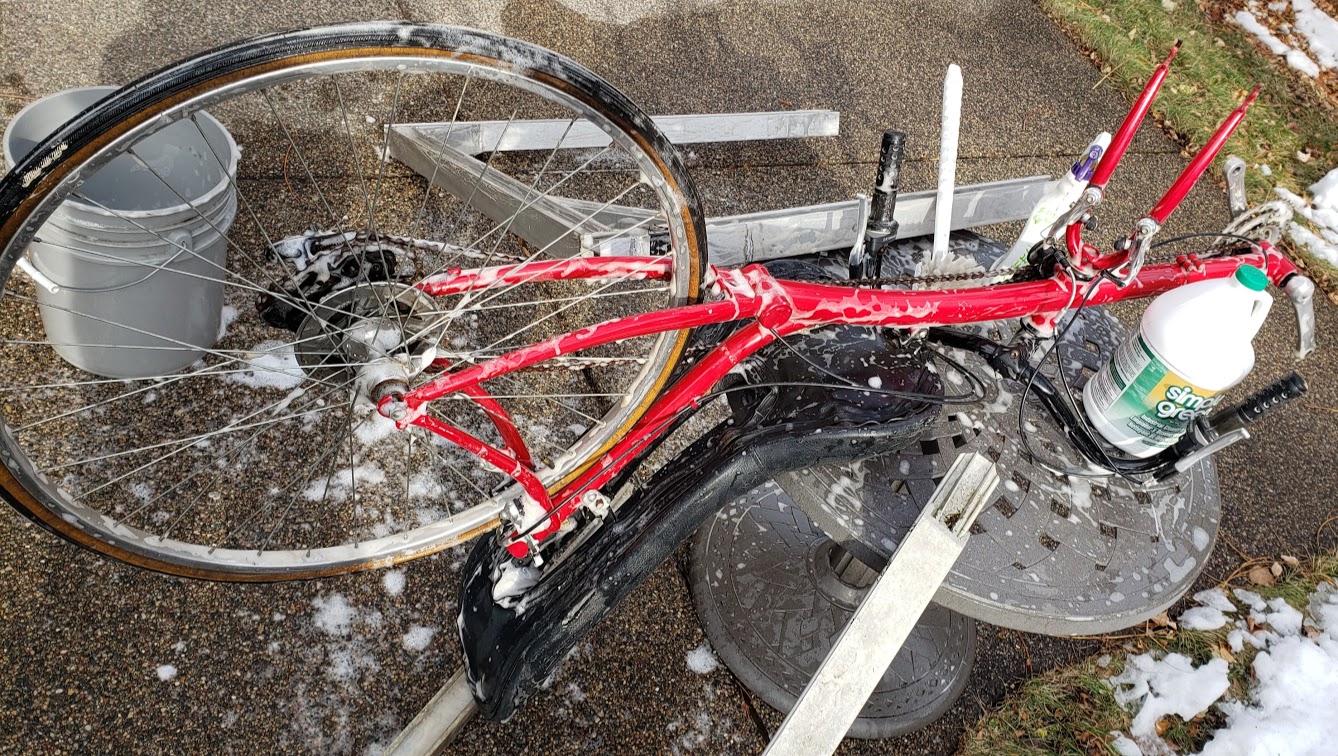
via a small make-over process...
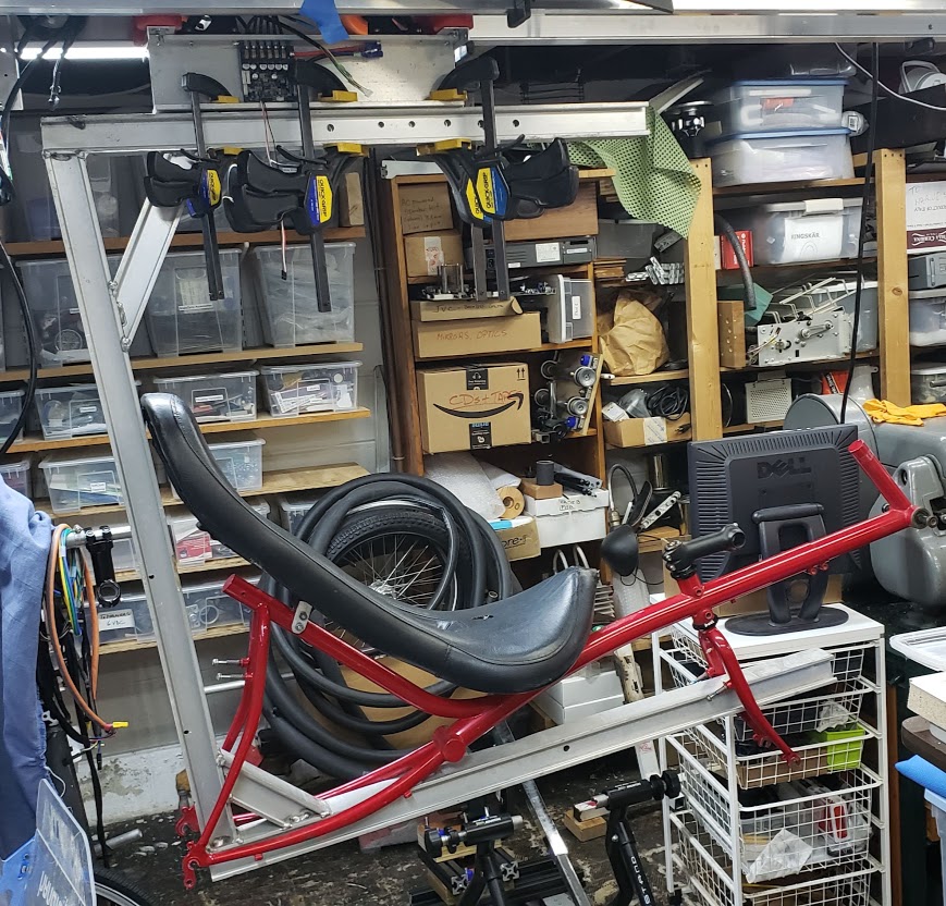
to being placed in the "C" frame to see how it might fit.
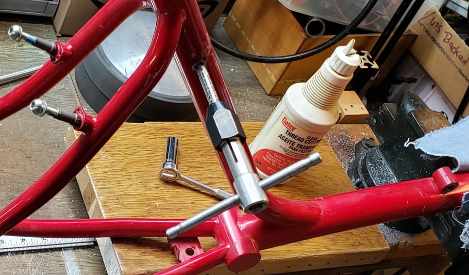
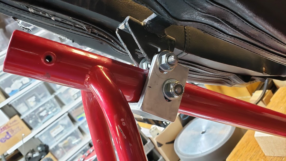
Having decided that this could work as a full scale prototype to test all of the sub-systems, it's time to mount the "red recumbent" frame to the "C" carrier. First we need to attach some hardware to the frame so it can be rigidly held, but still be easily movable. Since we don't yet know how things will fit together, we need to be able to facilitate the "trial-and-error" design process utilized by the Tringa team (HJ). Here we see a solid steel axle with spacers fitted to the rear dropouts, and an upper mounting bracket for the seat being made. The seat had been bolted to the frame, but it was too difficult to remove and re-attach it.
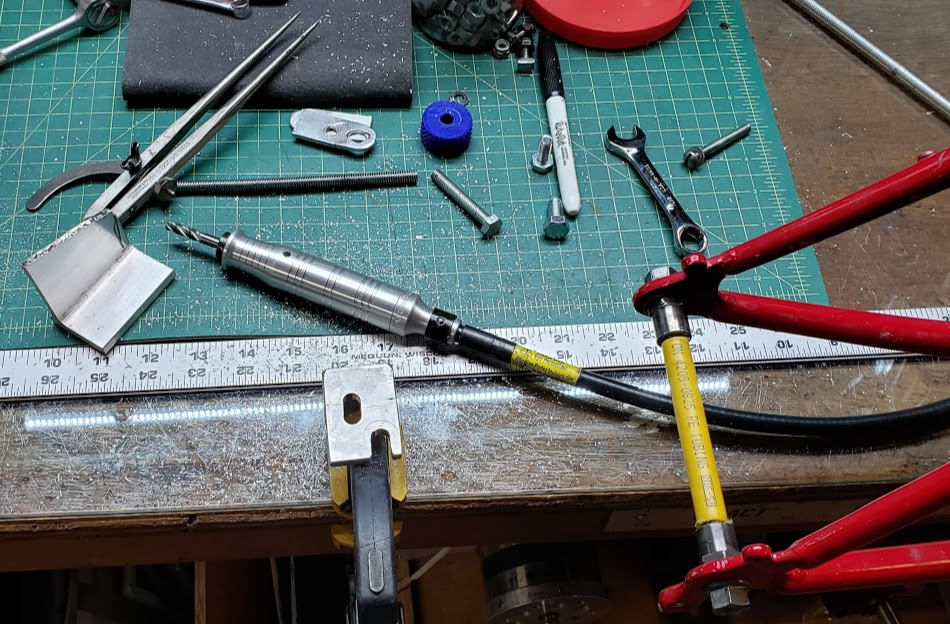
The front seat mount (on the far right side of the red frame, below) is a solid welded on boss, so we'll just leave that alone.
The upper seat mount are two inserts welded into the main tube, and they had become 'ovalized' due to some unfriendly engineering at some point during their life. After being reamed back into roundness, they gladly accepted a brand new 5/16" coarse thread.
Using a scrap piece of "U" channel aluminum with slotted holes allows some minor adjustments, as well as allowing quick removal without having to remove any nuts or bolts. The upper slots are open, so the seat just drops into the assembly, and two nuts are tightened with a 1/2" wrench.

eSkyBike Seat
Given the profile of the "C" platform of the ceSkyRide vehicle, a 'recumbent' style seat would most likely be the most appropriate seat style.
Rans seat
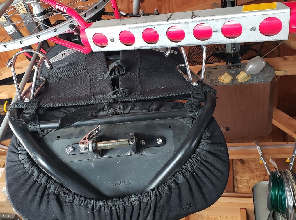
This version of the Rans recumbent seat is used by a number of commercially available recumbents, and has a well designed mounting system. It is also known as the "ReCurve" model when provided as an option for Bacchetta recumbents. It is designed for a more upright seating position, which is often preferred by beginning recumbent riders.
Here we see the U-shaped channel fastened to the Rans Rocket recumbent bike's main tube to accommodate the Rans style seat. The main tube is (~?) 2" (50mm?) in diameter, and the outside dimension of the square channel is 2 1/8". There are three points which fasten the seat to the bike frame. Directly underneath the bottom of the seat is a square clamp which fits over the U-shaped channel and is tightened with a hand operated cam-lock lever similar to those used to fasten quick-release bike wheel axles. The two other points are struts which support the rear of the seat and are fastened to rear of the bike frame.
eSkyBike Resistance Unit
The key to any successful 'fly-by-wire' based vehicle is that the human input controls have an extremely 'realistic' feel to them. The vehicle has to respond to the controls in an intuitive and natural way, otherwise the human rider will not feel 'in control', which is an unacceptable condition.
For vehicles which also need to simulate a human powered vehicle (e.g., a bicycle), there is the additional challenge of making the human rider feel as if she is actually providing the power to make the vehicle move. This involves the following two functional components, which may or may not be combined into a single unit:
-
A mechanical resistance unit which absorbs the energy/power provided by the human rider, and
-
One or more sensors which provide a signal that accurately describes the power being provided by the human rider. The sensors will typically measure torque (force) and cadence (time). The combination of these two measurements allows the calculation of the human's energy/power input in watts.
A computer on the vehicle is used to coordinate the input data from the above devices and generate the necessary data to the vehicle's controllers and motors. This has to happen in such a way that the rider feels as if their effort is directly and proportionally resulting the vehicle's movement. Success is indicated by a wide grin on the rider's face after a ride.
Here is a list of the various devices we have tried to use as a physical "resistance unit":
Resistance units/hardware.
UNDER CONSTRUCTION!!!!
Return to Top of Page
Return to Main Menu