Slap a motor on a vehicle, and just GO. That's the easy part. This page covers the factors that allow a person to get on a vehicle, take it for a spin, and gave a grin on their face when they get back after their very first 'test' ride. The key to the "grin effect" is an interface between the human and the machine that is comfortable, intuitive, and *safe*! These issues apply to *any* vehicle operated by a human which has some kind of motorized assist mechanism.
The following post by Justin on ES way back in 2013 summarizes the issues to consider, and are as true today (whenever that is) as they were then. Follow the link to read the full thread, which is chock-full of great information.
Post subject: Re: Weight Sensing Longboard with Inline Wheel Motors PostPosted: Thu Apr 25, 2013 11:31 pm Location: Vancouver ... I used to believe I preferred throttle control over a torque sensing pedalec style ebike. But then, once I started riding more ebikes that had nicely integrated pedalec I realized that for the most part this was a nicer and more natural control interface between the human and the bike, since it's using the same input (your leg power) that you already use. Similarly, since leaning is such a core part of how you maneuver a skateboard (or surfboard, snowboard etc) I think that it would be a more natural control extention for motor power than moving one of your digits across a throttle. If you've ridden a throttle controlled board, you learn quickly that you need to lean forwards first before you engage it or the board will shoot out from under you. So the leaning already has to take place, and the brain has to learn to do that first in anticipation of you hitting the throttle. In any case, our brains have a great way of figuring out control schemes and turning them into an extension of ourselves regardless of how they're implemented, so pretty much anything can work. Like gamers who achieve all kinds of delicate feats from pushing buttons on a keyboard or control pad, even though those button presses have nothing to do with the action going on the screen. We are used to pushing foot pedals to accelerate and brake a car, but why not instead have little throttles and buttons on the steering wheel for that? Or why have a steering wheel at all when you could use your feet to turn and then use your hands on a joystick to accelerate? I don't know if anyone's actually studying what is the 'best' way for a human to control a 2000lb vehicle, but given that we're no longer constrained by having to do everything with mechanical linkages like in the old days it's a question worth asking. -Justin
While it might not be intuitive, the brakes on an ebike are frequently different than the brakes on an un-assisted bike. The most common difference is that an ebrake will be able to automatically turn off the power coming from the assist unit when the rider applies the mechanical brakes. The second type of ebrake is best described as an "electrical" brake, as distinguished from the above "mechanical" brake. The electrical brake doesn't rely on the friction of two surfaces rubbing together to slow down the bike. To make matters even more confusing, this kind of brake actually has more in common with throttles than it does with brakes. Electrical braking will be more fully discussed under regen braking, as well as throttle types, below.
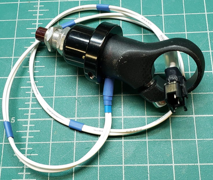
Seen below is a photo of DIY ebrake button built from a Grayhill (N.O.) momentary switch and a repurposed (sawed-off) bar end.
The switch was selected from the surplus bin for its positive clicking feel and sound, and the bar end allows the switch to be
mounted in the right position for operation by the index finger. It will be mounted right next to a thumb-operated throttle control. When used with a CA3, as we do here, the ebrake signal line is internally pulled high (5VDC) in the CA3, and activating the ebrake simply requires that the signal line to be pulled low (actively shorted to the CA3's ground). Grin has traditionally used a 4 pin JST-SM connector for the ebrake lines, with pin 2 being ground and pin 4 being the signal line, so that's the convention we followed here.
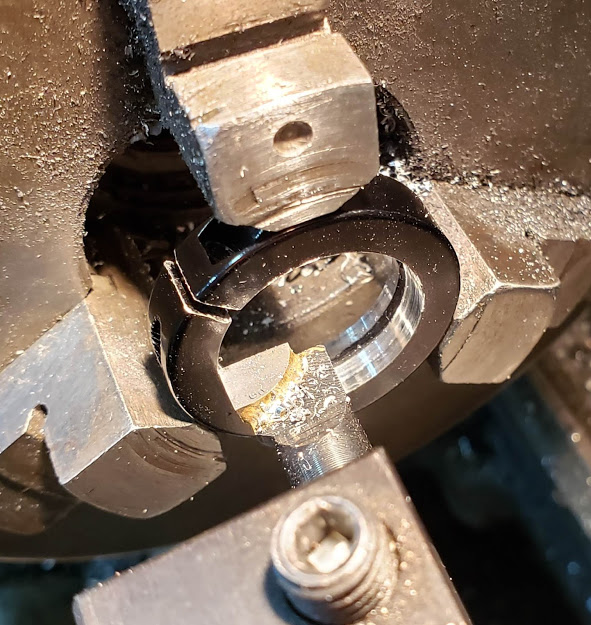
The momentary switch is held in place on the shortened bar-end via a clamping ring from a repurposed handlebar grip. One was a perfect fit as-is, the other needed a bit of machining to provide the proper clamping action for both parts.
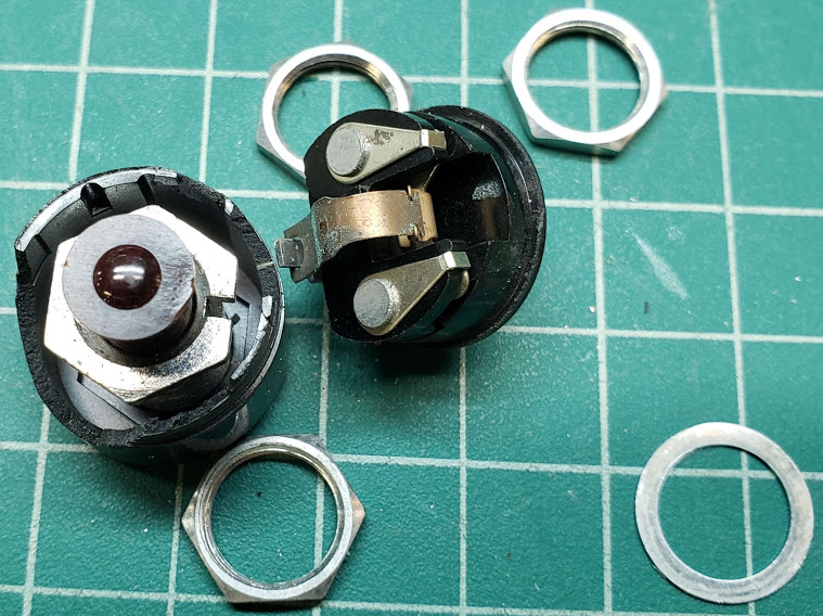
This photo showing the insides of the switch reveals why it feels so solid and has the positive clicking sound and feel.
Even though it was removed from lab test equipment back in the 1970's, it will likely outlive similar switches manufactured today.
Of course it's not a good idea to have the wind blow the bike over when parked and have the ebrake switch be the first thing
to hit the pavement.
See Cycle Analyst (v3) for CA specific throttle setup.
A typical ebike throttle, or any light electric vehicle ("LEV") throttle for that matter, uses sensors that are either resistive (like a Magura twist grip) or Hall Effect (like typical chinese twist grips or thumb levers). Resistive throttles use variable resistors to alter the throttle signal, while the Hall type uses small powerful magnets that move closer or further away from a sensor that responds to magnetic fields. No matter what type of sensor is used, any throttle device will supply the controller's "throttle" input port with a 1 to ~4.5 volt DC signal. This will ideally be an analog voltage signal, but digital ("PWM" and "PPM") signals are also used (See the VESC Controller Throttle Input section for more details about this). The 0.085-1.0 volt signal range represents a fully "closed" (neutral) throttle while the 4+ volts represents a wide open ("WOT") throttle. The exact throttle voltage signals will vary and depend on the controller, as well as other devices used on the LEV. Note that the use of the word "throttle" is borrowed from the internal combustion engine (ICE) world, where the "throttle" typically represented the "butterfly valve" in the intake barrel of a carburetor. Since the position of this valve controlled the power output of the engine, we've become used to the terms of a throttle being "open" or "closed" (or somewhere in between).
When the LEV is capable of proportional regenerative braking (see regen), an opportunity exists for the throttle to also become an e-braking control. This is an issue of convenience and safety for the rider. When used this way, the throttle must also be able to produce a signal that goes *down* from the 0.85 volt "neutral" throttle zone, hence the name "bi-directional". As the throttle signal approaches 0.00 (zero) volts, the vehicle slows down proportionally, following the throttle signal. The amount of slowing is proportional to the regen taking place, and depends on the combination of motor(s), controller(s), and battery capacity. Regen is typically expressed in units of negative watts. Note that regen braking requires a non-freewheeling motor (direct drive) and a controller whose firmware supports this feature.
For the bi-directional throttle, I'm thinking of a non-moving joystick-type lever fitted with strain gauges. When no pressure is exerted, the amplifier board we already have will output around 0.85 volts, which is the ebike throttle deadzone. Pushing the stick forwards will increase the output voltage up to around 4.5 volts (full throttle forward), while pulling back drops the voltage to below 0.85 towards 0.00 volts, which is full regen torque.
I did the first test ride of my new ebike outdoors on Sunday with a combination ebrake lever and thumb throttle, and the voltages are now spot on. While this works OK, it's more complicated than it should be since I have to 'crack' the ebrake lever to activate ebraking mode, then use the forward throttle to vary the braking force. NOT "intutitive", and it makes it harder to put a newbie rider on the bike and have them be comfortable on it. However, I can bring the bike from 35MPH down to a crawl in a matter of seconds with just motor braking, which is the point of this exercise. It's about 600 watts of ebrake power, which is plenty for "normal" uses. In an emergency I can still use the mechanical brakes (disc front, rim brakes rear).
If you've got any ideas about what kind of "stick" to use for a single control, let me know. I guess I should even entertain the notion of a sensored 'grip', since that might be more ergonomically useful. It should be comfortable for the hand, and be usable with a mitten for cold weather use. I've gotten pretty good with strain gauges, so I think I could fit them to nearly any kind of physical device. If there was an off-the-shelf bike handle device already out there that I could modify, that would be great as well.
But here we'll have a twist grip throttle that *doesn't move* (rotate). Simply trying to twist it one way or the other will either accelerate or brake. The advantage is that I have no moving parts, it water/weatherproof, and the 'detent' for the throttle neutral/deadzone position is automatically built-in and self-adjusting (the rider doesn't twist it in either direction). Sensitivity is fully adjustable via electronics. It's exactly the same technology I'm using where the whole handlebar is the throttle/brake combination; now just reduced to the grip on one end of the handlebars.
See this Strain Gages page on this site for their use in measuring human pulling effort to result in an e-assist throttle substitute setup.
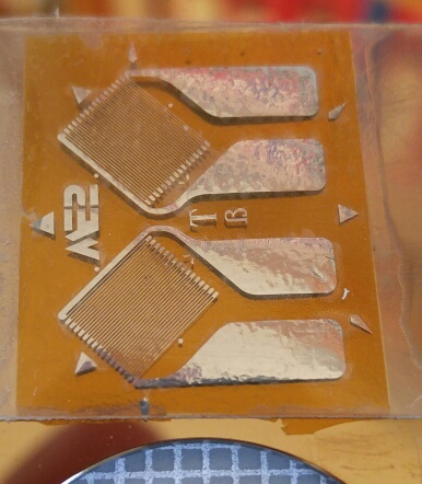
See also: strainblog.com page for measuring torque using their specially designed strain gages (shown in following photos). This site is sponsored by Micro-Measurements/Vishay (UK), but has great information.
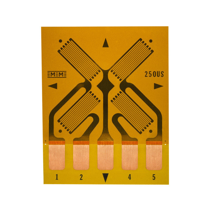
Use two of the following dual-grid, common-tab pattern [M-M/Vishay Dual-Shear (Grid) Pattern, 187UV], mounted diametrically opposed on the shaft, for a full bridge implementation. This can be more accurate than the single gage approach. The central common tab is for the signal output.
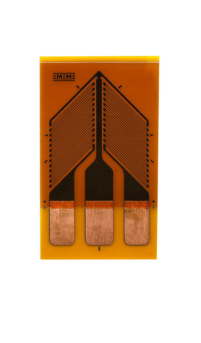
This youtube video by M-M/Vishay demonstrates the preferred method for mounting two gages at 90 degrees to each other and 45 degrees from the shaft's centerline. Repeating this with two additional gages 180 degrees (opposite side) on the same shaft would allow wiring for a full wave bridge configuration. At this point I'm *assuming* that we can pick up an output signal from the bridge that goth both up and down so we can translate it into a throttle/brake signal following the shaft being twisted in one direction and then the other. This must be *proven* before this idea for a bi-directional throttle is valid.
Justin answering ES questions:
Justin: "You really want the hand opposite the throttle to be the one that activates the regen button, ideally just via an ebrake swtich [sic] on the brake lever, but otherwise a stand alone push button on the left side would do the trick if you have the throttle on the right."
[Editor/hj: Note that the typo for "switch" above is actually fairly common and yields some interesting results when your force a search for this spelling on ES.]
Other: "Having gone through the various alternatives in my head, I feel that a second left-handed thumb throttle would be the best way to implement proportional regen."
Justin: "That would also work just great. There is no problem at all parallel connecting two throttles together and combining their outputs. Since the throttle output signal can source current but it can't sink current, then whichever throttle has the higher voltage signal is the signal that dominates. So simply split your throttle wires to go to both the left and right hand throttles and you'll have [it] made."
MrDude_1 wrote: "I do have one question though.. what size is the power out plug on the Cycle Analyst? the one intended for running lights? I have a bluetooth adapter I use for the serial data, and I want to run the power off of that plug. (I have a DC-DC adapter to drop it to 5v)"
Justin: "It's a common DC 5.5x2.1mm barrel plug, and you can get the matching jack for that at many places."
The label "PAS" (Pedal Assist System) on this site primarily refers to cadence counter mechanisms. [Technically speaking, the term PAS includes any mechanical system that senses the rider's efforts related to pedaling.] These cadence counter devices simply determine when you begin pedaling, how fast you are pedaling, which direction you are pedaling in, and when you stop pedaling. Cadence refers to how fast you are pedaling, and is expressed in units of RPM (revolutions per minute). Systems that detect "how hard" you are pedaling are arbitrarily covered under the torque_sensors section.
Refer to Grin's comprehensive PAS page for a great overview of the available "off-the-shelf" PAS hardware and how to use it. This page also covers CA3 Aux Input Devices and how to best use them with PAS setups, as well as setting up basic PAS sensors with CA firmware. If there are issues with PAS and the CA, this page should be your first stop. Remember that specific products come and go, so always search the web for what's currently recommended.
Any e-assist mechanism that needs to know exactly how much effort is being expended by the rider will need some kind of torque sensor. Human effort can be approximated somewhat by simply measuring movement. This could be pedal rotations, i.e. "cadence", in a traditional bicycle, or the length and frequency of a rowing stroke in an alternate propulsion system. However, here we focus on measuring the actual force ("torque") exerted by the rider. We break down these torque sensors by their 'off-the-shelf' availability as finished commercial units vs. making custom devices using strain gages and load cells..
There are numerous torque sensing hardware devices available for use with LEV e-assist systems, especially if pedaling is primary human input method. Some devices designed for pedaling may be modified for other uses.
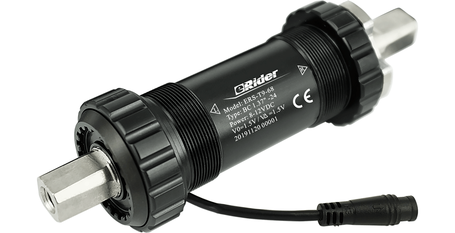
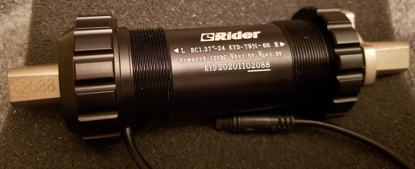
The eRider bottom bracket is an off-the-shelf drop-in replacement for the existing bottom bracket found in many stock bicycles. It measures both the rider's pedaling force (torque) and cadence (pedal RPM). A distinct advantage of this sensor is that it does NOT require any modifications to the bike frame into which it's installed. Many other sensors require drilling a hole into the bike's bottom bracket frame component for the exit of the sensor's wires. This is also the first such sensor available for less than $100 (in 2020).
Photo showing the 68mm standard width "T9" model sensor. The threads are the stock 1.37"x24 tpi version, and a standard splined BB removal tool will fit this unit.
The 3.15b [Release: 3.15b1 2021-03-18] firmware version of the CA3 includes this torque/PAS sensor as a predefined menu selection. You can, of course, also enter this data manually into previous firmware versions as a 'custom' torque sensor. (5) 7365 - Add 'ERider' Torque Sensor option and remove 'Cycle Stoker' option This versions adds the new 'ERider' torque sensing BB as a predefined torque device option for setting PASD->SensrType. This new setting automatically applies these other PAS device settings for proper operation of this BB: PASD->PASPoles = 18 poles PAS ->AsstAvg = 18 poles PASD->SignlType = 1-wire PASD->DirPlrty = Forward PASD->TrqScale = 70 Nm/V PASD->ZeroTorq = 1.5V
(7) 7909 - Increased Max PAS Poles to 36 with support for ERider_T9 The maximum number of PAS poles has been increased from 32 to 36 in order to support the latest ERider-T9 torque sensors which have 36 poles. A new torque sensor preset (ERider_T9) was added to support these bottom bracket devices with the following preset values: (The other values are as above for the 18 pole eRider BB's.) PASD->PASPoles = 36 poles PAS ->AsstAvg = 36 poles
The manufacturer's website is at https://www.erider.com Follow the site's menu links to go to the "sensors" page, where various versions of this bottom bracket torque sensor can be found.
This is the actual unit we got in 2020 directly from China, when stocks worldwide were extremely low.
Return to Top of Page Return to Main Menu
The TDCM bottom bracket is an off-the-shelf drop-in replacement for the existing bottom bracket found in many stock bicycles. It measures both the rider's pedaling force (torque) and cadence (pedal RPM). It's five-wire output goes directly into any compatible computer or controller and allows the calculation of a throttle signal used to control the motor. The manufacturer's website is at tdcm-motor.com.
Functional diagram of the TDCM bottom bracket:
TDCM torque bottom bracket Manual (PDF, 26 pps, 2014)
The following summary is based on ~ 05/04/2015 emails with Grin and Harry Wigglesworth:
Excitation voltage; current consumed by TDCM BB +5/6 VDC Input Voltage, 25 mA Power Consumption NOTE: Grin Tech (ebikes.ca) "define and specify specific specifications to work with their Cycle Analyst controller, based on a 12V input voltage." The CAv3 connector describes it as 10VDC.
Signal voltage returned from BB: The effective voltage span (signal size) is ONE VOLT (1V), falling into the ~ 2.4V to 3.4V DC range.
Maximum torque measured on pedals: The maximum force applied to the petals, beyond which there is no change in the output signal voltage is ~40Nm
Harry Wigglesworth Head of European Operations www.tdcm-motor.com Tel (TW): +886-9-81-529-661 | Tel (EU): +49-178-239-0088 Skype: harry.wigglesworth | harryw@tdcm-motor.com
Reminder about thread directions for bottom brackets and pedals. Both use non-standard ("reverse") left-hand ("LH") threading on one side, and standard right-hand ("RH") threading on the other. The side on which the reverse LH thread is used, however, is different. This is done to keep these assemblies from coming undone while pedaling.
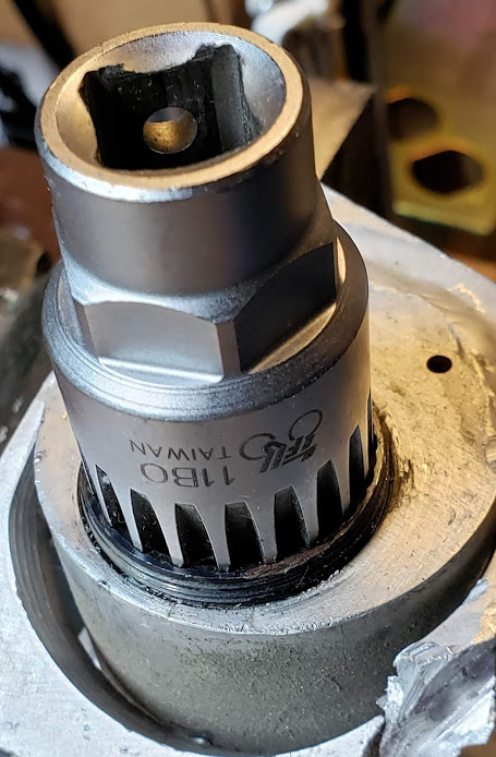
Showing the retaining cup on the right ("drive") side of the BB. This uses a standard right hand (RH) thread, and is inserted to its full depth.
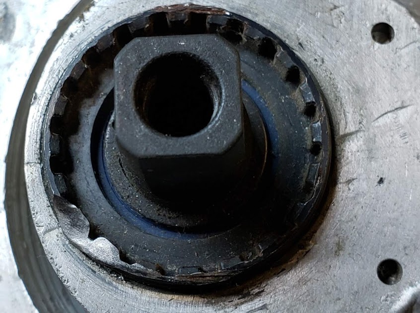
Photo of a standard bottom bracket ("BB") removal tool, in this a special 1/2" drive socket made to fit the retaining cup(s) of many currently used BB's. Park Tool has several tools for this purpose as well.
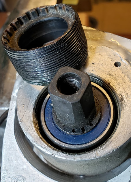
With the retaining cup removed, the drive side bearing (with blue rubber protective shielding) is now visible. Optionally, for a complete disassembly, a snap-pliers is used to remove the snap-ring, and the bearing then can slide off. This second step is normally NOT necessary to install or remove this BB.
Now showing the left (non-drive) side of the BB. This retaining cup uses left-hand (LH), or "reverse" threads. The snap-ring on this side MUST be removed to allow the axle assembly to be removed towards the drive side. A two-part bearing will slide out this side once the snap-ring is removed. The cup on this left side is removed using a DIY two-pin tool, or carefully with any kind of thin pry bar. This cup is used for adjustment only, and is usually loose enough to be screwed out by hand -- assuming the threads are clean and not damaged.
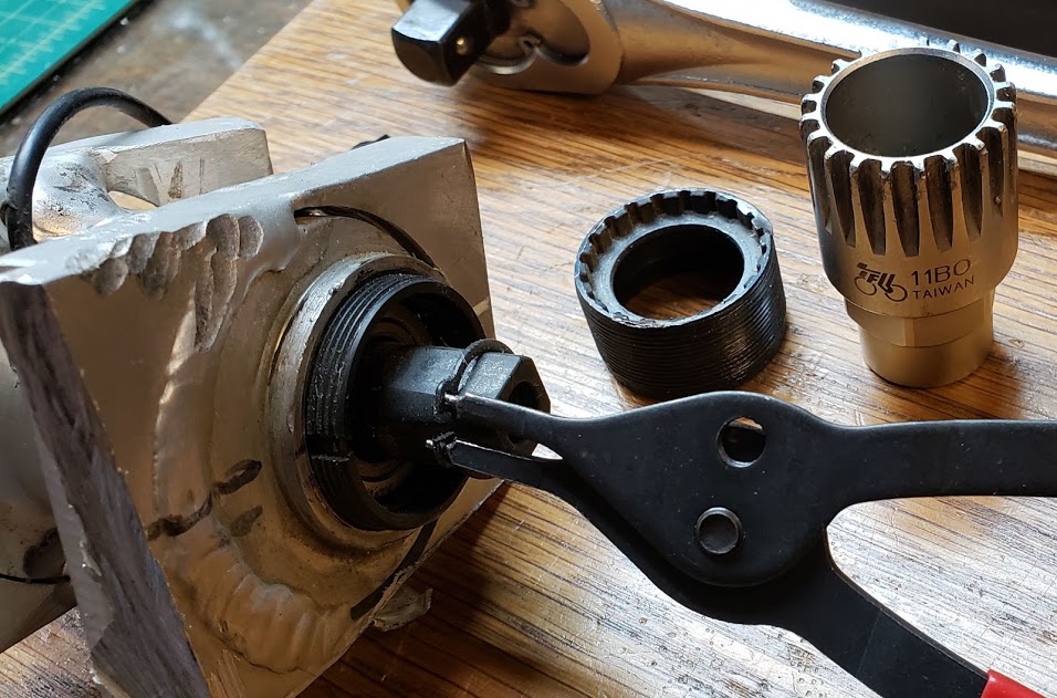
Photo of the TDCM BB shaft assembly removed from the housing. When this unit was originally installed in this custom housing, the signal wires were pinched by the retaining cup and severely damaged (although still functional). On removal however, the wires needed to be cut so the assembly could be extracted. The pinched wires, just barely seen near the edge of the housing, haven't yet been extracted.
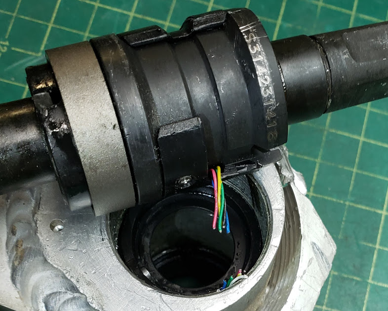
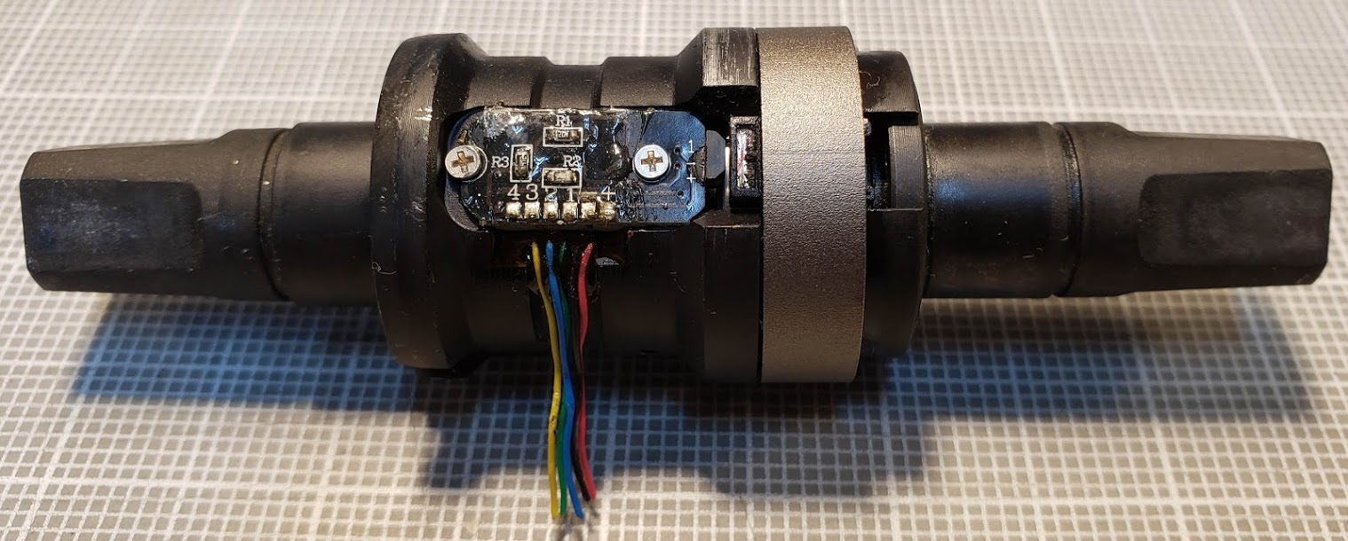
Photo of sensored axle assembly removed from the BB housing 'shell'. The five signal wires have been cut and will need repair. The circuit board is normally covered by a semi-circular plastic cover held on by one tiny phillips-head screw (as seen above). On the right side of the circuit board you can see the trapezoidal shaped 3 wire Hall Effect sensor and magnet combination which is used to measure the torque applied to the crankshaft. It does this by detecting the slightly changing distance between the Hall sensor and the magnet.
TDCM uses different pin defines and cable numbers depending on the specification - see page 6/7 of Manual. TDCM female connector specs (PDF, 1 pps, 2014) TDCM male connector specs (PDF, 1 pps, 2014)
Emails between Tringa, Scott O., Grin Tech (Justin et al.), and TDCM (Harry W).
Return to Top of Page Return to Main Menu
The Sempu units are chinese clones of the TDCM and earlier bottom bracket units which had torque and cadence sensors built into them. They have become increaingly reliable are frequently used due to their lower prices. GRIN now supports their use.
Return to Top of Page Return to Main Menu
The TSDZ is actually a mid-drive motor that replaces a standard bottom bracket, much like the Bafang 8Fun and BBSHD series which is a better known example of this type of motor. The reason this 'motor' is placed in this off-the-shelf torque sensor category is because parts are available which might possibly be used to solve torque sensing challenges based on standard bottom bracket configurations.
The following shows a kit ($500) for an ebike conversion based on the TSDZ2 mid-drive motor. It remains to be seen whether or not it would be suitable for a combination resistance unit-torque sensor.
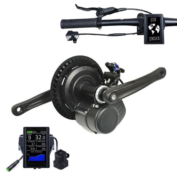
Site that supports this ecosystem and source of the above photo: https://www.eco-ebike.com/collections/tsdz2-open-source-firmware-osf-products
https://github.com/OpenSource-EBike-firmware/TSDZ2_wiki/wiki/How-to-calibrate-the-torque-sensor
Why it is important to calibrate the torque sensor? Almost every torque sensors on TSDZ2 is different and reports different values for the same weight on the pedals. Some have low sensitivity / very short linear zone only up to 15 kgs while others up to 45 kgs, as also different sensitivity on left and right pedals. As comparison, riders like me can do peaks of 40 or 60 kgs on pedals without lift the butt from the saddle. Why this is important? because if you want the best motor response and natural feeling of a bicycle, the torque sensor needs to work/be linear the best possible. Also, this is the only way to trust on the measurements shown on display for the pedal human power. Here is TSDZ2 1 and TSDZ2 2 the torque sensors measurements - the torque sensor of TSDZ2 2 is way better!!
Return to Top of Page Return to Main Menu
Read this brief tutorial from National Instruments (Application Note 078) to get a technically competent understanding of how strain gages work. While there are some formulas with funny math symbols, you can easily skim over them without compromising your understanding. It's a 12 page PDF file, but even reading just the first few pages will provide you with the basics.
Note that "gage" is generally considered to be the American spelling, while "gauge" is the British form. Either form is in common usage. Strain gages are typically used in pairs so that you can combine both tension and compression forces in one sensing device. This approach also doubles the sensor's signal strength because while one gage's resistance goes up the other's goes down. The gages are connected so that the measurement equals the total change.
Justin's advice is "For the best sensitivity with strain gauges, you want to build a full bridge with two gauges in compression and two in tension."
From the same ES forum thread referred to previously, he says the following: (Posted: Thu Mar 19, 2015)
Strain gauges are just resistors etched in a zig zag grid, and when the surface of the metal is under tension, it stretches, elongating and thinning the resistor wire causing its resistance to increase tinyest amount (less than 1%). Similarly, when the metal surface is under compression, the resistive wire gets shorter and fatter, lowering its resistance by a fraction of a percent. It's one of the most deceptively simple and ridiculously accurate electromechanical sensor devices, but it does require a high precision low drift instrumentation amplifier to turn the bridge output into a 0-5V signal. I already detailed the amplifier circuitboard and strain gauge operation on this thread here I got most of my strain gauge education from Richard Nakka's rocketry website way back in the day. 15 years later his website is still there and still a great reference: nakka-rocketry.net
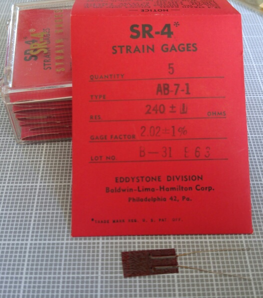
Strain gauges are manufactured by Vishay (very high end, expensive), Omega (good, but "cheaper"); Revere; Micro Engineering (the kind we got). For a very extensive reference to all things "strain gage" -- see this online PDF reference by Omega Engineering: PRACTICAL STRAIN GAGE MEASUREMENTS
The measure of the gage's resistance change with strain is GAGE FACTOR, GF. Gage factor is defined as the ratio of the fractional change in resistance to the fractional change in length (strain) along the axis of the gage. The gage factor is a dimensionless quantity, and the larger the value, the more sensitive the strain gage. Gage factor is expressed in equation (see original PDF). The gage factor for Constantan and nickel-chromium alloy strain gages is nominally 2, and various gage and instrumentation specifications are usually based on this nominal value. This means that twice the strain results in twice the change in resistance -- a strain gage is "linear".
Same model as used on the original moon lander in 1969.
Return to Top of Page Return to Main Menu
This section covers the mechanical process of "gluing" strain gages to some substrate. Useful material from Keith J. Wakeham, B.Eng, M.Eng, kwakeham@gmail.com: re Strain Gages on a Bicycle Crank Keith has a history of using strain gages in the bicycle world, and somewhere around 2014 ended up working for 4iiii.com, making "power meters", which do just what we want in terms of measuring the rider's torque and cadence input, but just *report* this data to the rider instead of translating it into a throttle signal. Solder on fine wires [directly to the foil of the strain gage], usually 30--36 AWG wires [I can use the very fine pre-tinned (silvered), insulated wire I have in 6" precut lengths] to the pads. You'll see my new version using bondable terminals as it's easier to bond small wires to gauges and big wires to the terminals. It also provides strain relief. Two gauges are wired in series and measured against the mid point of a voltage divider creating a half wheatstone bridge arrangement. [I think Keith put one strain gauge, at 120 ohms, on the top edge and one on bottom of a crank arm, connected in series to make up one side of the wheatstone bridge, and two additional 120 ohm resistors (small ones) in series to complete the bridge] Well, I don't want to break the gages so lets protect them. Epoxy, 5 min kind. Very flexible and soft compared to metal and the superglue glueline. [looks to be a Permatex brand, general purpose two part expoxy, "Perma Oxy"]
Return to Top of Page Return to Main Menu
This is a compilation of Suggestions, mostly from Keith Wakeham:
- work on stack of clean paper, discard layers as you go along - thoroughly clean area - mask off area (optional) with good tape - degrease with acetone, wipe off in one direction; - degrease before sanding to prevent forcing grease into sanding grooves - sanding to bare metal, not much finer than 400 grit, use wet sandpaper (vishay recommends mild/diluted phosphoric acid) - some recommend sanding in circular patterns to prevent "channels" that can affect strain readings - neutralize with light ammonia water (ok on skin) - "neutralizer" - find a clean piece of plastic/glass as a 'staging area' (this is the surface you use to stick gage to tape before application to host) - do not grab a gage by the fine resistance lines -- grab corners near foil/solder pads, and only with tweezers - put strain gage on staging area, top side up - use "strain gage instrumentation tape" (i.e., weakened, transparent, 'reusable' tape) - put the tape over the gage lying on the staging area, starting on one end and "laying" tape over gage so no air bubbles are trapped - when top surface of gauge is bonded to the sticky side of the tape, peel back one end using shallow angle - this is intended to remove both tape and gage from the staging glass without the gage separating from the tape or bending - align the gage over the host, using the 'alignment marks' if necessary to get the right position - press one end of the tape down and using your thumb, smooth the tape down forcing out all air bubbles - verify position of the strain gage on the host - at shallow angle (again), peel back the gage with its carrier to expose the bare metal of the host - take 'off-the-shelf' superglue (cyanoacrylate) [vishay of course has special stuff for all of this] - put a line/bead of glue at the beginning of the gage space, and then 'roll out' the gage/carrier over the glue [much like Polaroid film packs used to be processed by being squeezed between two rubber rollers which evenly distributed the chemicals -- the key here is to get just the right amount of glue to evenly cover the gage and not have too much/excess squeezing out, making an ugly glue line]. You're aiming for an 8 micron layer of glue... - apply steady pressure over the gage for at least a minute -- maybe 5 mins; test will be if edges stay down if trying to pick up with pick - after glue has set (allow 24 hrs for *full* cure), peel back carrier tape, this time at oblique angle, since gage stays on metal host - pull back the tape just barely past the solder pads, leaving the rest of the tape to protect the gage while attaching the wire leads - solder fine wires to gage solder pads; Keith uses 34 ga. copper "magnet wire" which has a fine (enamel) insulation layer - you do NOT want leads to touch bare metals, since it will skew the ohms reading, plus pick up lots of RF, since metal acts as antenna - do not use any wire that's already been bent! - Avoid ground loops (may occur if the shield of the strain gage cable is connected to ground at *both* ends; just ground at the amplifier side) - cable capacitance (mF) plays an important role with long extension cables and should be as low as possible - HBM says use solder tip temp of 250-270 degrees Centigrade - all parts to be soldered must be "wetted" with flux -- which is colophonium dissolved in "methylated spirits" (alcohol?) ... - solder has "colophonium core"? - "tin" both the solder pads and the wire ends; Keith applies liquid flux directly to gage pads before tinning them - when solder on pads is cool, remove excess flux with rosin solvent (alcohol?) - flux is mildly conductive, so it can act as a bridge/shunt/short between solder pads, which kills the gage's accuracy! - flux cleaner can also be conductive, so allow it to completely dry before testing - check for continuity between gage and ground (host bare metal) -- you do NOT want ANY continuity here (more than 10K megaohms!) - protect the strain gage using air dry polyurethane; still have masked off area ... press wires down against metal to keep a low profile - maybe use a second layer of polyurethane; you don't want to have any conductivity for this protective stuff (5 gigaohm resistance is ok!) - I wonder if the black plastic self-bonding tape (Duluth Trading) would be good for protecting strain gage on round handlebars? -
And the following is great advice from user "RPLaJeunesse" on the "All About Circuits" forum [https://forum.allaboutcircuits.com/]. When we used some of our strain gage circuits on ebike frames, the EMI/RFI was so bad that the signals were unusable without special efforts, including filter caps on the signal input lines.
RPLaJeunesse 23 Jul 2021 at 9:55 AM #22 Load cells are very lossy [I consider any device with an output that is below 1% of input to be quite lossy.] transducers, the output is in the low millivolts. Any stray electromagnetic noise could be readily picked up by those 30cm connections. Excitation pairs (+ & -) should be twisted together, Signal pairs should be twisted together and, for good practice, twist the pairs together. The goal is to minimize and loops in the wiring. Using shielded cable can also help. Cat-5 shielded cable is a great possibility, albeit with more wires than needed. Another noise mitigator is to add a filter capacitor across the signal lines at the HX711, for an example of how to do this look at this HX711 connection schematic by SparkFun.
With all of the variables present in a strain gage installation, it's necessary to establish a level of confidence in what is being measured. One way to do this is to apply a predetermined mechanical input or strain on the system (such as hanging a bowling ball with a known weight on the handlebars) and comparing that to the indicated signal output. Another is to simply change the resistance of one leg of the Wheatstone Bridge by some known amount(?R). If this change is accomplished using a high value resistor connected in parallel ("shunted") over one of the bridge's legs, this is known as "Shunt Calibration." This method lets you compare the measured output of the bridge with the expected value, and make whatever corrections are needed.
A "load cell" is simply a mechanical device with one or more strain gages already built into it.
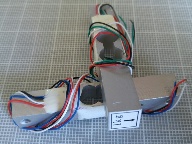
Typical wiring for load cells: (if only three wires, the negative input/output wires are common)
INPUT wires: (Excitation, typically 3.33-10VDC) Red+, Black-
OUTPUT (Signal) wires: Green+, White-
These load cells are from postal scales rated for 1Kg and 5Kg. Because they have 4 wires, we know they use a full bridge strain gage configuration.
These chips are differential amplifiers with a very high input impedance. They include the TI INA-122, INA-125, INA-128, INA-129, and the AD623, AD8553, AD8556, AD8221; MAX4194, LT1167.
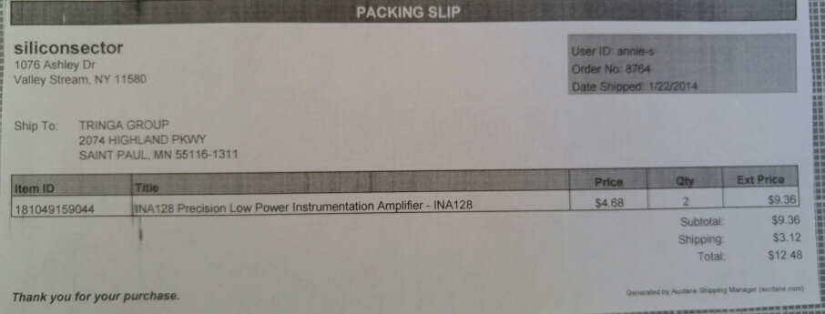
Digikey sells the TI INA128P [Part Number INA128P-ND] for $11.31 (Feb 2014)
Deb got 2 of these, but for $4.68 each via US seller on ebay. These chips are standard 8 pin DIPs.
 An instrumentation amp is a package containing two op-amps to filter/buffer/clean up the input voltage/signal, and another op-amp that multiplies the cleaned up input by a factor of "x" (gain), which is controllable by the user of the instr. amp via an external resistor (R-gain).
Another property of an instrumentation amplifier is that it has a high common mode rejection ratio, which means that if there are very quickly changing values in BOTH SIGNAL INPUTS, it dampens/smoothens/averages these changes.
The idea is to focus the measurement on the small differences (voltage swings) between the two inputs., not on any larger signals common to both inputs.
[Greg Lewin: http://youtu.be/dEViQBsleqs]
An instrumentation amp is a package containing two op-amps to filter/buffer/clean up the input voltage/signal, and another op-amp that multiplies the cleaned up input by a factor of "x" (gain), which is controllable by the user of the instr. amp via an external resistor (R-gain).
Another property of an instrumentation amplifier is that it has a high common mode rejection ratio, which means that if there are very quickly changing values in BOTH SIGNAL INPUTS, it dampens/smoothens/averages these changes.
The idea is to focus the measurement on the small differences (voltage swings) between the two inputs., not on any larger signals common to both inputs.
[Greg Lewin: http://youtu.be/dEViQBsleqs]
Return to Top of Page Return to Main Menu
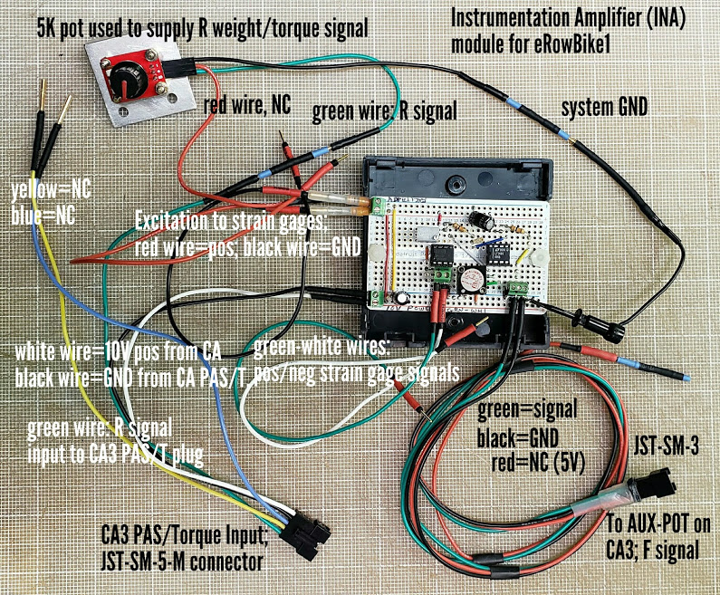
See dedicated page to Tringa's INA
Because the eRowBike1 does not use PAS as part of its e-assist strategy, we decided to design a simpler (fewer inputs and outputs) strain gage amplifier circuit. We assumed that we'd obtain our torque signal from a Wheatstone bridge strain gage configuration that was excited at either 5 or 10VDC, either which is available from the CAv3. The amplifier module's output would be mapped into the 1-4VDC range, maing it compatible with a typical ebike throttle.
We selected an Instrumentation Amplifier chip that only needed a single voltage (rail) input, and would allow sufficient gain and filtering to utilize the expected 4-5 millivolt (mV) signal coming from the strain gage array.
Return to Top of Page Return to Main Menu
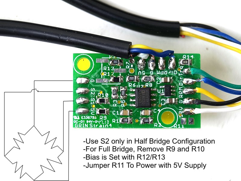
We also got a completed Instrumentation Amplifier board from Justin at ebikes.ca in Vancouver, BC for $40.
This board will support both a half-wave and a full-bridge strain gage configuration. It uses a high quality dual op-amp, which Justin happened to have on hand for CAv3 manufacturing.
Has onboard linear regulator for use with 6-16V DC supply Can be run from 5V by putting jumper on R11 Default gain of 1000x.
Set by resistors R3/R6 and R8/R5
For Half Bridge, connect signal to S2 For Full Bridge, remove resistors R9 and R10, and connect bridge signals to both S1 and S2
 Online documentation for this board
Return to Top of Page Return to Main Menu
Return to Top of Page Return to Main Menu
This heading covers the several possibilities involved with arriving at the single, critical data signal which controls the movement of an LEV: -- the throttle signal going to each motor's controller.
Credit for this outline is given to many members on the ES forum, such as Justin (above), and specific posts and threads including this one by user "Avitt".
An "ideal" e-assist for lightweight electric (assist) vehicles (LEV's) will need to consider the following conditions, and would likely involve a "mix" of all three sensor inputs:
1) Takeoff from stop For both convenience and safety reasons, getting an LEV rolling smoothly and predictably from a dead stop is critical. When the light turns green, you want to be clear of that intersection as quickly as possible. With a PAS sensor alone, there is some delay before the power comes on. If the LEV is using pedals, this is typically a half-revolution of the cranks. A LEV is heavier due to the addition of the motor, controller, battery, and "beefed up" components. If 'downshifting' is available, it will typically need to have been done before stopping -- not always an option used. This condition is best addressed by use of a throttle or torque sensor. Note that many control systems using a throttle require the LEV to be already moving (2-3MPHP, or "walking speed") for safety reasons. This severely limits the use of the throttle to assist in getting going from a dead stop. There is no such limitation for torque sensors. 2) Maintaining desired speed Once safely underway, there are many radically different expectations that need to be met by the LEV's assist sytem. The rider may want a lot of exercise, or none at all. The only way to meet the needs on this spectrum is to have an assist system that can be 'dialed in' from fully "OFF" to "WOT" (wide-open throttle). If using torque sensing only, the rider must be constantly supplying some amount of force to maintain the desired speed. If using a 'mixing computer' such as the Cycle Analyst, there is a lot of room for adjustment, but because most sensors are limited in their detection range, this amount of required force is often relatively large. A "throttle only" system can meet this condition in that a rider can use as much assist as desired, but it requires constant attention and decision making. (Some systems support a "cruise control" mode in which speed is maintained at a level determined by holding the throttle at a constant level for several seconds.) A PAS only system requires that the rider is constantly pedaling, or rowing, or moving whatever mechanism this particlar LEV is using for propulsion. It may not require much effort, depending on the level of assist that is selected, but it does require constant motion. The advantage of PAS is its intuitive interface -- the faster you move, the faster you go. The amount of exercise you get is dialed in via the "assist level". In some jurisdictions (countries), this PAS "Pedalec" system is a legal requirement, so the rider has no choice about its use.
At this point it should be fairly obvious that my preference for a universally ideal system (if it could exist) would be an LEV that included sensors of all three types: manual throttle, torque, and cadence (PAS). A programmable computing device, such as the Cycle Analyst, will accept the input from all sensors and mix/blend/condition them into a single signal going into the controller, which determines when and how much the motor(s) spin. Note that 'garden variety' controllers for BLDC motors, such as the "Infineon" type and their derivatives, will typically have limited inputs, including 'throttle only', in which case a 'mixing' device is mandatory if you want to use multiple sensors. Having the ability to combine all sensor inputs upstream from the controller, and giving the controller a single 1-4 volt DC "throttle" signal, may make the tuning process for the LEV much simpler. The computer determines the performance characteristics of the LEV, and optionally provides levers, buttons, etc. to the user/rider to customize their riding experience based on circumstances or their preferences on that particular ride.
Grin's CAv3 computer is a powerful tool for managing all of the possibilities involved with sending a single throttle signal to the traction motors' controllers. Following is an excerpt from the ES forum in which Justin and another forum member discuss the ways that the LEV can be moved from a dead stop using only a torque signal (no PAS signal involved). This would allow the use, for instance, of a torque sensing bottom bracket to signal the motor to start turning with no other input signals needed.
Justin makes the point that the throttle and torque analog input signals can be connected in parallel. The use of diodes isn't necessary because the throttle can't pull down the 0-5 volt signal, but it can pull it up.
1) Connect the manual throttle's output/signal line directly to the CAv3's throttle input connector
2) Connect the torque sensor's output/signal line to the CAv3's throttle input connector via a 500 ohm resistor.
This will 'favor' the throttle's signal, if active, but allow the torque sensor to behave exactly like a throttle if it's the sole signal source.
One thing to remember is that when doing regen braking via the CAv3, the throttle input signal has to be pulled below 0.8 volts somehow.