| eRowbike Resources | |
|---|---|
| eRowbike1 | Original prototype of the eRowbike series, utilizing the strain gauge sensored handlebars. |
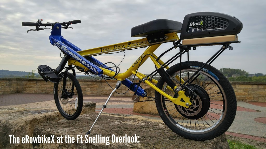
| eRowbikeX | Second prototype of the eRowbike series, using the BionX proprietary assist system. It utilizes a strain gauge sensored rear axle. |
| Power Lever | The traditional power lever assembly on all original Rowbikes share similar components, including shock cords, chains, etc. |
| Seats | Seating for all LEV's |
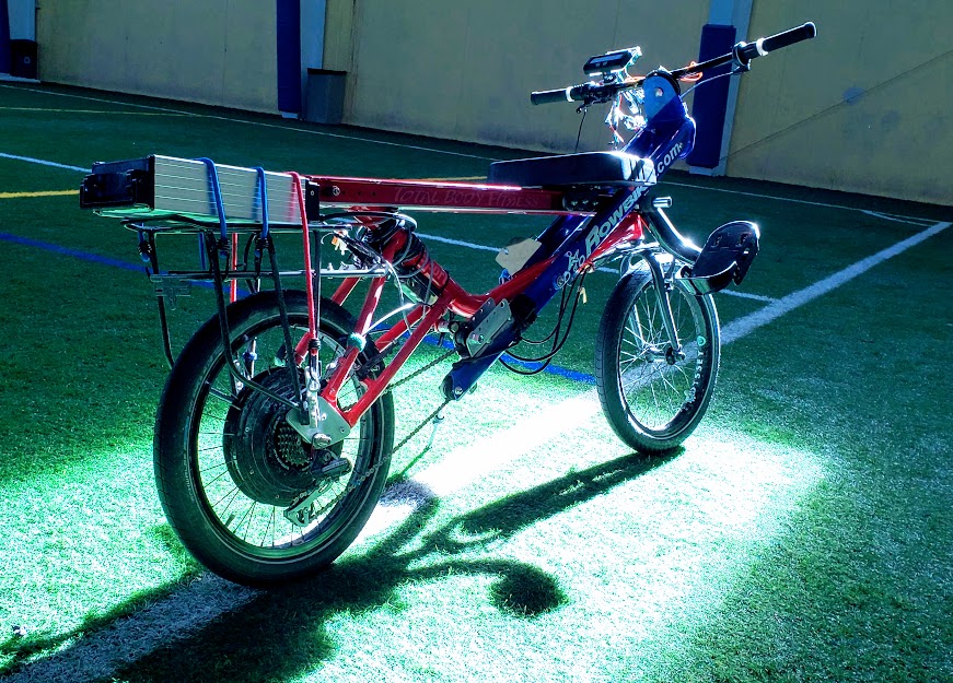
This is the original prototype of the eRowbike series, using a simple twist-grip throttle to make the bike go. This is using the Lyen controller and the 13S/48V eZee Flatpack lipo battery mounted in the rear rack, which is not an ideal location. My broken left knee is evidence of the fact that putting too much weight over the rear wheel leads to poor handling characteristics. This photo was taken on November 8, 2013. The torque plates on the rear axle have not yet been installed.
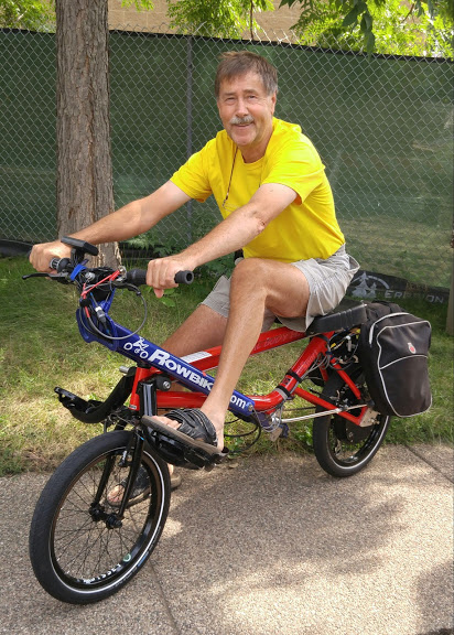
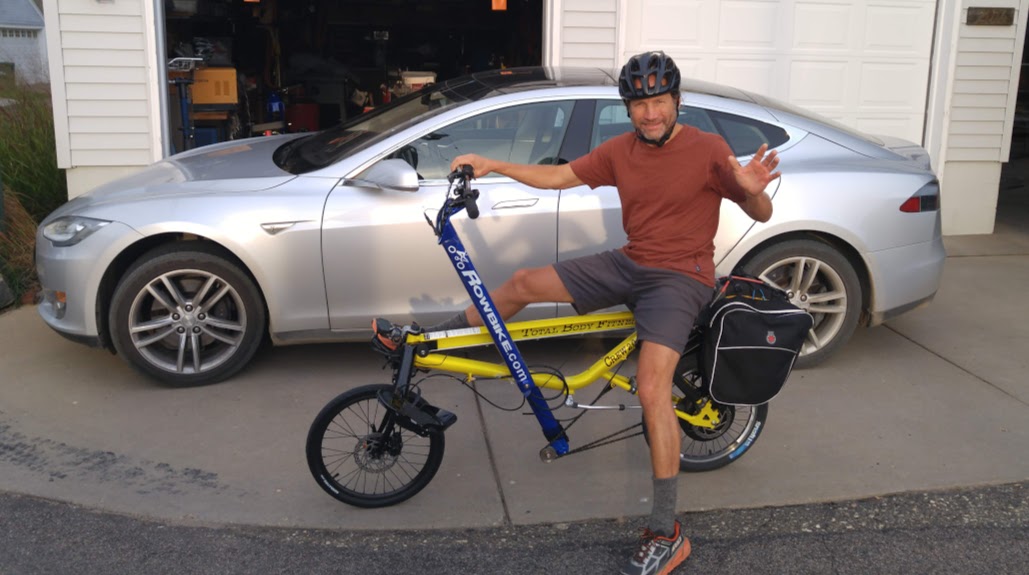
In the photo below, taken on August 25, 2016, we still haven't switched to the 'instrumented handlebars'. We have gotten to the point of appreciating the e-assist on the Rowbike, however.
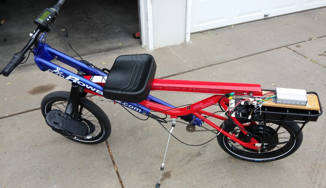
In the following photo, the strain gauge sensored handlebars have replaced the manual throttle of the original prototype. The Lyen controller has been replaced with a Grin Phaserunner, which allows a smooth, proportional regen ebraking. The improvement in braking is probably more significant than the recovered energy, but the Phaserunner is a great controller and it's in an ideal (smaller) package. The original $800 battery no longer supplies enough current, so we're experimenting with different replacement batteries. We're gravitating towareds 14S/52V batteries, as shown below.
| eRowbike1 | CA Skateboard Settings | This sections documents the settings used on the eRowBike1 when running the Skateboard firmware. |
|---|---|
| Motor | This version of the prototype has used two different motors, both by Crystalyte. The first was the HT3525 and the second (is) the H3548 (UFO) motor. |
| Controller | The original controller used was the Lyen modified Infineon. The current controller used is the original series Phaserunner by Grin. |
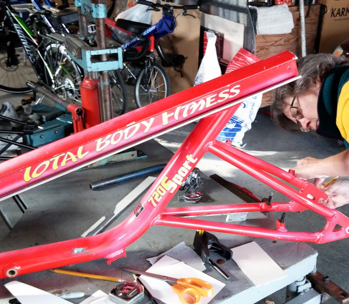
The Rowbike frame is aluminum, and using a high torque rear hub motor with only axle flats to prevent spinout is too risky. Here Debbie designs bolt on torque plates to provide additional support for the axle flats. The plan was to use stainless steel, but the prototype 0.25" aluminum plates have held up without any wear, in spite of full torque acceleration and regen braking for testing purposes. The finished torque plates can be seen in the photo above.
Return to Top of Page Return to Main Menu
While this version of the eRowBike worked reasonably well, we didn't have enough access to programming necessary parameters of the proprietary BionX system used. Additionally, the company went bankrupt shortly after our development work got well underway.
Scotty on eRowBikeX at 2074 Highland Pkwy in Sept 2015. The panniers hang over the top of the 48V/13S BionX stock battery. All of the weight on the rear was never a good idea.
Return to Top of Page Return to Main Menu
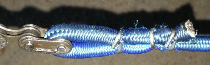
Detail showing the use of "hog clamps" to make the tight loop that connects the shock cord to the Rowbike chain. The M6/0.25" shock cord is a tight fit for the standard 7-speed chain used, with a stock half-link connector to join the two. Experience has shown that two hog rings are more than sufficient to keep the loop intact. Make the connection as small as possible to minimize the resistance of the chain-cord junction traveling over the roller in the bottom of the power lever. The shock cord is 12 feet long and cut with a hot wire to prevent fraying or unraveling of the shock cord covering.
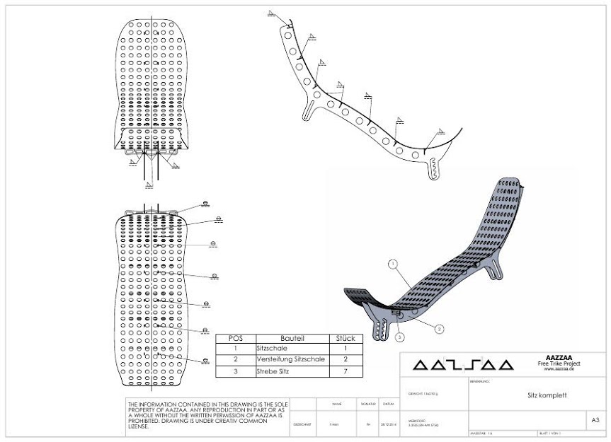
The following photo is a sample CAD-type drawing showing a recumbent seat designed for an open-source trike project. The labels are in german but fairly obvious (I can provide English translations if necessary.) This seat's profile is very close to a recumbent ideal for a variety of light vehicles. While the seat's profile is fixed, the two mounting points allow for adjusting the angle of recline. My preferences as to neck/head support is that it is available to support the neck, just below the helmet line (if worn). It should not be so far forward that the neck is constantly contacting it. A rider's neck will quickly become strong enough to support the head in a relatively vertical position, allowing free movement for pleasant and safe riding, using the support only to overcome periodic fatigue. Watch the video further down this page on how this works out when pedaling a boat.
See download links to actual drawing files. Also, google "aazzaa" for more information about this project.
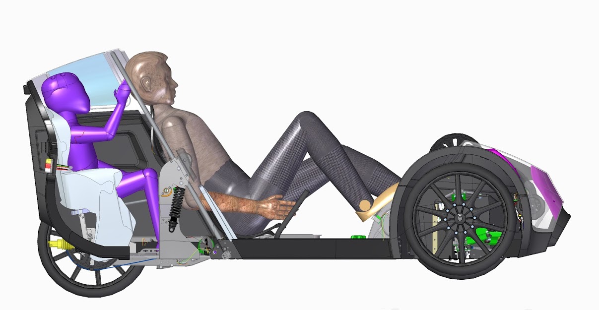
Here we see the application of the above seat type being used in the Norwegian Podbike, an e-assisted velomobile which in 2020 was in the final testing stages before beginning full production as a commercial product.
Water biking on the Mississippi River near Hennepin Ave bridge in 2019 with Scotty. At the very beginning of the video, note the correct position of the neck/headrest on the Wave Walker seat. It is just slightly back and out of the way of the normal neck/head position while active, but there for resting when needed.
Video from Scotty suggesting mesh seats on aluminum framing. (This *.MOV video file needed the Apple Quicktime plugin for normal web browser display. I used the "ffmpeg" binary on the linux server to convert this file to an *.mp4 compatible codec file.)
Return to Top of Page Return to Main Menu