| CA Documentation for our use with specific vehicles or drive systems | |
|---|---|
| General Setup for CAv3 (all firmware types) | Firmware settings shared among our light electric vehicles. |
| CA Skateboard Settings | Settings used on the eRowBike1 when running the Skateboard firmware. |
| CA Programming for TDCM BB | Settings used on vehicles using the TDCM bottom bracket PAS hardware device. |
| Using CA with Bafang BBSHD | Adapting CA JST-SM and Anderson connectors to Bafang's HIGO plugs. |
| CAv3 General Resources | |
| ebikes.ca | Grin Technologies: inventor/developer/manufacturer's website; info@ebikes.ca Justin Lemire-Elmore of Vancouver, BC; He prefers email over PM's on endless-sphere.com |
| CA User Guide on ES | "Unofficial" User Guide written/maintained by the late teklektik on Endless Sphere forum |
| 2016 CA User Guide as PDF | "Unofficial" User Guide (2016, v3.0-e) by the late teklektik on erowbike.com |
| Grin page for CA | For "Version 3" of the CA, typically referred to as "CAv3" or just "CA". This page includes links to (Setup utility, FTDI drivers, etc.) |
| List of CA Setup Settings | For CA version 3.1 firmware. This annotated list covers all possible settings. |
| CA Programming Kit | DIY wiring adapter making it easier to program the CAv3 when it's not on the vehicle. |
| Teklektik's page on ES | tek's 2WD Electric Yuba Mundo Build; has TONS of useful ebike info |
The CA can calculate speed, distance, and motor/wheel RPM's based on incoming +5V/high and 0V/low pulses on the yellow 'speed' wire located in the 6 conductor CA-DP bundle. The pulses can be generated by either:
If you don't care about *distance* data, you can leave the stock CA-DP plug connected to the controller and get motor RPM data from the controller. On the CA, set the wheel size (circumference) to 1666 mm and the display units in Km. This will convert the 'ground speed' display to 'motor RPM' in 10's of rpm (e.g. 35.6 kph = 356 rpm).
To get speed and distance data via the controller for a hub motor, simply supply the motor's pole-pair count plus the wheel circumference in millimeters and let the CA do the math. The controller 'knows' the motor's RPM from looking at Hall sensor data if available or possibly by reading magnetic fluctuations. The distance calculations will be as accurate as the wheel circumference settings, which unfortunately vary slightly with tire pressure and other variables. A smart phone with GPS tracking is a convenient tool for calibration. Also select "Miles" vs "Kilometers" for US use. Note that you *must* correctly set the #PolePairs parameter for the BLDC motor being used in the CA, otherwise the displayed data will be wrong.
If you don't see a speed reading on your CA, you need to troubleshoot using Justin's advice given on the ES forum [Post: "Re: Cycle Analyst V3 preview and first beta release", by justin_le » Jul 28 2017]
Return to Top of Page Return to Main Menu
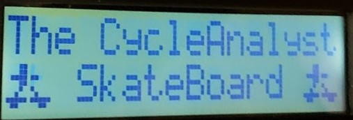
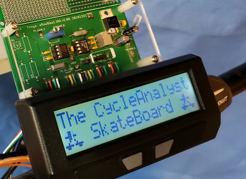
We began using Justin's (Grin Technologies) beta skateboard firmware on 20 Jun 2017, using the CA Setup Utility v1.43 to flash "skateboard.hex" firmware to the eRowbike CA3. When successful, the CA's boot screen looks like this:
This "Skateboard" firmware doesn't use the standard "Throttle" input (in fact, connecting a physical throttle to the CA3 with the Skateboard firmware installed throws a boot error "PC02102 ... T_ERR ...". This firmware's SETUP must have its [ThrI-> Cntrl Mode] set to "Passthru" to have it work correctly (see THROTTLE setting below). The realtime display for [SETUP THROT IN] will not display any live throttle *in* values, although the CA3 will display live throttle *out* values which accurately represent the actual values sent by the CA3 to the controller's CA-DP input. Note that we do optionally use a physical throttle (gripshift model) with this firmware, but the "throttle" device actually becomes a variable regen electric brake, so it functions exactly opposite its normal use.
This version of the firmware in the CA ignores cadence (pedal RPMs) and makes all of its throttle adjustments based on two torque inputs (front/"F" and rear/"R"), each of which can have its own "Gain" calibration in millivolts per pound (mV/lb). We use the F torque signal for making the bike go and the R torque signal to make it stop.
For the eRowbike1, the torque data for the "F" input to the CA firmware comes from a "load cell" consisting of four strain gauges mounted on the erowbike1 handlebars. The strain gauges are configured in a full-wave Wheatstone bridge and are supplied with 5 volt excitation current from our instrumentation amplifier (INA) board. There's no particular magic to what strain gauges are used, as long as they can provide enough of a differential signal to accurately reflect the rider's effort. As a matter of fact, for testing purposes we have used a cheap, stock 5Kg "load cell" imported from China to simulate the pull on the handlebars, and it works just fine. Since the CA firmware can compensate for both scale factor and voltage offset, nearly any device can be used for this torque input sensing.
When the rider exerts a positive pressure ("pulls") on the handlebars, a very small positive and proportional voltage signal is sent from the handlebars to the INA. Justin on his longboard was getting a 4-5 millivolt (mV, equal to 1/1,000 volt) signal when a person stood with all their weight over one of the trucks (axles), and for him that was plenty of signal range to play with. He'd configured the Grin4 amplifier board to have a gain of about 500, while we're using ~700. Our INA board is very similar to Justin's Grin4 board, except that we use a dedicated instrumentation amplifier chip instead of a dual op-amp. Once filtered and amplified into the 1-4 volt range, the INA board sends this signal to the CA's AuxPot input (the JST-SM 3 pin connector with the white housing). The CA in turn uses this "F" torque signal, in combination with the "R" torque signal to compute the actual throttle signal sent to the controller. A relatively higher "F" signal in relationship to the "R" causes an increase in the throttle voltage, while the reverse is also true.
While not necessary to basic operation, we have taken Justin's advice and added a gripshift "throttle" and repurposed it as a variable regeneration electric brake. To slow down, just apply the throttle as if you were accelerating. The mechanical brakes are unaffected by this, and will rarely need maintenance due to lack of use. See the R torque configuration section below for details.
Photo of prototype INA board currently used on eRowBike1
The eRowbike1 follows typical ebike conventions by having its "total throttle range voltage" (TTR/V) mapped between ~ 1V and 4V, when referenced to the system ground. The BLDC controller used on the eRowbike1 (Grinfineon/Phaserunner, etc.) expects to see this voltage range on its own dedicated throttle input, and could thus be used without the intermediate CA3 if desired. This approximate 3 volt range (TTR/V) becomes 3,000 when measured in millivolts (TTR/mV), which is the unit of measurement this firmware expects to be programmed in.
For the erowbike1 configuration, our values are based on the following:
Pull Pounds for WOT (pp/WOT): 30 lbs
The number of pounds of pull (pp) at which the throttle is effectively wide open (WOT) is somewhat arbitrary, since different riders will have different levels of strength. Ideally, pp/WOT would be adjustable by the user in real time. For testing purpose, we're assuming an average rider who will exert a maximum pull of 30 pounds on the handlebars. The rider can of course pull harder and make the bike go faster, but there won't be any more assistance provided by the motor.
F signal voltage in mV when pp/WOT pressure is exerted on the handlebars: 3,000 mV
This number is derived from the fact that a 3 volt increase (from 1V to ~4V, see above) on the throttle signal wire represents the entire range between a closed throttle and wide open throttle (WOT). One volt is equal to 1,000 millivolts (mV). Practically speaking, there is probably no adjustment necessary for this value, since this ~ 3 volt range is a nearly universal standard in the ebike world.
Signal strength gain provided by the INA board: 722
This amplification gain is a hardware adjustment made on the INA board which probably needs no additional adjustment once the correct relationship is established between the sensitivity of the strain gauges and the particular handlebar installation.
The key adjustment to determine how much assistance is provided by the system ("assist factor") boils down to the number of millivolts per pound (pp/WOT) in the active forward throttle range (TTR/mV). In this skateboard version of the CA firmware, this adjustment is known as the "Assist Factor" [Cntl-> Asst Fctr (mV/lb)] and is calcualted as follows:
[TTR/mV] /divided by/ [pp/WOT] e.g. 3,000 mV / 30 lbs == 100 mV/lb
Note: Justin says no throttle voltage is sent until skateboard moves min of 2mph but I have no idea how the skateboard firmware knows the skateboard is moving. In our case, the assistance is provided from a 'dead stop' condition.
Return to Top of Page Return to Main Menu
As used on a skateboard, not the erowbike1:
There are two sets of Wheatstone configured strain gages. One set on the front and one set on the rear trucks of the skateboard determine acceleration or deceleration. If the weight placed on the front truck is greater than the rear, the board moves forward. The converse also applies. Each Wheatstone bridge sends its raw output (in millivolts, typically 4-5mV) to an amplifier circuit which after filtering and amplification sends its output (in volts, typically 1-4V) to the CAv3/skateboard firmware which *mixes* the inputs and sends a single throttle signal to the computer. According to Justin, "the control algorithm is quite simple, the code measures the front and rear weights, subtracts them, and then this difference is added to the throttle output signal."
[Justin]You'll hook up the load cell of the rowbike to the front weight sensor (the aux input), and for the rear weight sensor you'll hook up any kind of throttle or potentiometer device to control braking and regen. You can still have the ebrake input line on the brake levers, but you could also just have a thumb or twist throttle and when you turn that it simulates weight on the rear sensor causing the CA's output to go into increasing regen territory for variable braking control.
To summarize:
F/Front strain gage's output goes to "Aux-Pot" input to CAv3 (the "white" JST-SM3).
R/Rear strain gage's output goes to "Torq" input of CAv3 (the green wire on std PAS/TORQ plug)
Return to Top of Page Return to Main Menu
There are three main SETUP sections which are used to tune the skateboard firmware to the desired response and performance. They are as follows:
1) Basic control ("Cntl");
2) F torque sensor;
3) R torque sensor. Each of these three sections contains several specific settings.
See the corresponding sections below the following tables for explanations of each setting.
| Cntl-> | |
|---|---|
| Min Weight (lb) | 0.5 |
| Asst Fctr/"G" (mV/lb) | 66
This was originally 45 with Crystalyte HT3525 and is now 66 to accommodate the higher speed winding of the Crystalyte H3548motor. Typical values will likely be between 40 and 100 mV/lb. |
| FRNT SENSR-> | REAR SENSR-> | |
|---|---|---|
| Max Fault (Volts) | 4.66 | 4.66 |
| Min Fault (Volts) | 0.10 | 0.45 |
| Scale (lbs/Volt) | 12.4 | 100 |
| Offst (Volts) | 1.11 | 0.90 |
This is the minimum amount of pull (in lbs, pp) the rider has to exert on the handlebars before any assist engages. This is mostly a safety feature to prevent the erowbike from taking off if a rider simply bumps into the handlebars or steers it while walking next to it.
In the original application for the skateboard, this weight was a substantial number, reflecting the approximate weight of a human rider who would have to be standing on the board before any assist would kick in. For erowbike use, this weight will be substantially smaller, with 0.5lb working fine during intitial testing.
The "assist factor" (G* on CA console) determines how much assistance the motor provides in response to the rider's pull on the handlebars. The higher the assist factor, the more throttle will be applied for the same amount of pull. From the rider's point of view, a higher assist factor makes the handlebars feel more "sensitive". Elsewhere in this documentation (e.g., see Frnt-Scale) we have determined that 3 volts (TTR/V) are required to obtain wide-open throttle (WOT). Expressed in millivolts, 3 TTR/V becomes 3,000 TTR/mV. Lets assume the rider exerts a 30 pound pull on the handlebars. If the assist factor were set at 100, this 30 pounds of pull would result in the erowbike going as fast as it could (WOT). If the assist factor were set at 50, the erowbike1 would go at half-speed when a 30 pound pull was exerted. See the calculations below for examples.
25 mV/lb times 30 pp == 750 mV (0.75V) of throttle
50 mV/lb times 30 pp == 1,500 mV (1.5V) of throttle
100 mV/lb times 30 pp == 3,000 mV (3.0V) of throttle <-- this is wide open throttle (WOT)!
When we did the first "on-the-road" live testing of the system on 5 Feb 2019 in an indoor sports facility, we used Assist Factor values ranging from 40 to 100. We changed the firmware settings on the fly using the CA's two buttons for programming, starting with 40, and then trying 60, 80, and 100. The eRowBike1 was equipped with "balloon" type tires, and the surface, while totally flat, was a fairly deep plush astroturf, resulting in an above average rolling resistance.
All of the above was done with the original HT3525 motor, which has a 'high torque' winding.
While our primary concern was the resulting subjective "feel" of the bike, we also used the CA to see how the various assist factor settings affected the actual power (in watts) being sent to the motor (a high-torque wound Crystalyte rear hub motor). At a 'G40' setting, the three test riders were experiencing a very noticeable assist level that translated into about 300 watts of power. When bumped up to G60, the peak watts ranged up to about 750, with 600 being more typical. At a G80 setting, the amount of assistance felt by the rider increased dramatically, making it fairly easy to hit the near-maximum speed of 20mph on a long, smooth power stroke. The typical watts of assistance ranged from 750 to 900. Increasing the level to G100 provided additional and noticeable assist, but not as dramatic. The number of watts over the G80 setting was probably only about 100 watts. Over 2.5 miles of these indoor tests, the maximum number of watts (AMax) the CA registered was a bit over 27 amps. Coupled with the steepest voltage sag to 48 volts with the battery we were using, this results in 1,296 peak watts.
The AMin (minimum number of amps) was -5.54, reflecting a relatively modest amount of electric regen braking. This was not surprising given the high rolling resistance and not needing to make any quick stops.
Return to Top of Page Return to Main Menu
This value must be slightly higher than the maximum voltage sent by the INA board to the CA under normal circumstances. The INA board when connected tends to "pull down" the voltage on the F torque line, while the CA tends to pull it up via a "pull-up resistor" to the 5V supply voltage. The purpose of these "Fault" (both Min and Max, Front and Rear) settings is to keep the motor from running away with the vehicle in the event that certain faults occur in the throttle/torque hardware. A value of 4.85 volts will be appropriate.
This just needs to be a value higher than zero, since a zero volt level might never be reached, even with a fault condition. For both F and R *minimum* fault voltages, a reasonable number would be half the offset value, since the 'offset' value is basically the 'zero' voltage level for the relevant torque sensor. This may need to be modified if the torque reading could go into the negative range under normal circumstances. Since the front offset with our standard gaged handlebars is ~ 1.10 volts, 0.50 volts would be a starting point. Remember however that *pushing* on the handlebars will make the torque reading go into the negative range to a certain extent, and we don't want that to register as a fault, so we'll use 0.10 volts.
Think of the "Front Scale" setting as a "multiplier" -- the number of pounds per volt. This setting represents the relationship between how hard a rider has to pull on the erowbike's handlebars to result in a wide-open throttle (WOT). The handlebar pull force is measured in pounds and WOT is measured in volts. We can represent this relationship as "Pull Pounds for wide-open throttle" (pp/WOT).
The difference between a closed throttle (no assist) and WOT is approximately a *3 volt* increase of throttle signal. This number of volts, which typically is mapped into the absolute 1-4 volt range, is by common ebike convention considered to be the active, or "total throttle range voltage" (TTR/V). Signals below 1 volt might be used to activate braking/regeneration or simply ignored. Signals above 4 volts, considered to be a WOT, are typically ignored until they approach 5 volts, at which point they trigger a software defined throttle fault condition. Our software always reacts to a throttle fault condition by returning the throttle signal to neutral (~ 1V). For the skateboard firmware on the erowbike1, this main signal is fed into the CA's Aux-Pot (green) wire (see "Connections" above). This Aux connector brings out 5V (pin 1) and GND (pin 2) the same way the JST-SM3 (black) "Throttle" connector does.
To complete this "Frnt Scale" calculation we take the number of pull pounds (pp/WOT) and divide by the number volts in TTR/V required to achieve the maximum e-assist (WOT). This can be expressed as follows:
[pp/WOT] /divided by/ [TTR/V]
e.g.
30 lbs / 3V == 10 lbs/V == Frnt Scale
[Justin] For the scaling factor, you'll be able to calibrate it so that more or less the lb. display on the front sensor is the same pounds as you are pulling on the handles of the rowbike, so it will be meaningful units. And the data output rate of the CAskate code is 11Hz, so if you log the data with an analogger or laptop you can see the force curve of each rowing stroke with OK resolution, kinda like what they have on the rowing machines at the gym.
Initially using the formula above gave us a front scale factor of 10 pounds per volt, and that clearly put us into the ballpark. But the 15.4lb bowling ball only weighed about 12.0 pounds on the SETUP FRNT SENSR "preview" screen, which displays the "live" value of the weight on the handlebars. Increasing the front scale value to 12.4 resulted in the 'reference' bowling ball weighing 15.5 lbs, within 0.1 pound of what it actually weighs -- close enough. At this weight, the CA is showing a voltage of 2.37V. Using the new scale factor resulted in a very linear and proportional relationship between applied and indicated weights along the entire range of 0 to 47.7 pounds. At this upper weight, the INA output is at its maximum of 4.99 volts. At 0 pounds, the voltage is 1.10~1.11, which is the front "offset" from zero. If we don't want to reach WOT with a pp of less than 50 pounds, we could make the handlebars "less sensitive" by reducing the gain in the INA module, and then readjusting the front scale factor accordingly.
Think of the "Offset" value as the "tare" value used to "zero out" a weighing scale. The strain gages' output is processed via the INA module, which itself is programmed to output a voltage range between ~ 1.10 and 4.20, to roughly correspond to the standard ebike throttle range. If we use a front offset value of 1.10 volts, the CA will equate this to the handlebars not having any weight (pressure) applied to them. With the correct front *scale* factor applied (see above), the handlebars become an effective digital scale when the CA is in SETUP FRNT SENSR "preview" mode. [Justin: "The preview shows the voltage on the sensor and the currently scaled weight in pounds. Inside you set the weight offset and scaling factor (which you can easily calibrate by standing on the truck."]
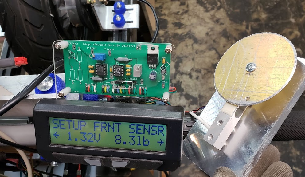
You set the Frnt Offst value by going into the "SETUP FRNT SENSR" screen, which will display the currently set offset value on the left side, and the number of pounds of pull (pp) the CA currently thinks are applied to the handlebars on the right side. Note that this is a "live" value and will change as pressure is applied to the handlebars. Make sure there is no pressure on the handlebars, and then press and hold the right CA button until the weight display on the right side goes to "0.0lb". This will update the offset value for the front sensor.
In the photo above, the handlebar strain gage input was replaced by a cheap Chinese 5Kg "load cell" (as used in digital scales). While the replacement load cell would need to have the SCALE and OFFSET parameters adjusted to put out approximately 1.00 volt at 0.00 pounds, pressing on the 'scale' platform (the round metal disk) made the motor spin just like pulling on the handlebars.
Return to Top of Page Return to Main Menu
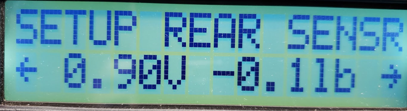
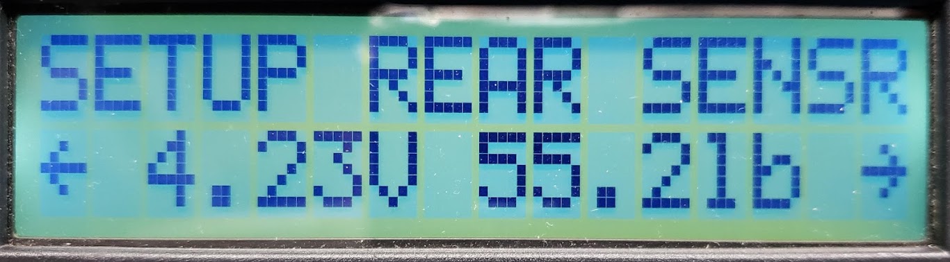
The photo above shows the "zero" weight (torque) setting of the rear sensor -- or at least as close as we can normally getting by holding the right button down to tare/zero the current state of the input device in its unloaded state. The corresponding voltage at that zero setting needs to be ~ 1.00 volt (between 0.80 and 1.10) to be in the throttle neutral zone. The photo below shows the fully loaded torque sensor at near maximum voltage. The indicated weight of 55.2 pounds can be increased by changing the SCALE value (see below). Since we're using the R torque device simply to provide the desired braking force, we don't care whether or not the weight display bears any relationship to actual pounds.
Set this value to less than 5.00 volts, but more than the maximum voltage achieved by whatever torque device is being used at any given time. In the example above, an appropriate setting might be 4.85 volts.
This value would typically be slightly above zero, but below the operating minimum. A setting of 0.45 volts should work fine.
See above under "Frnt Scale" for a general explanation. The key difference for this Rear Scale setting is that the input is a simple 5K potentiometer instead of a strain gage bridge's signal via the INA module. The 5K pot is acting as a voltage divider between 5V and GND, and can generate an effective voltage range of 0 to 0.44 volts in the CA's TORQ section, which the skateboard firmware uses to counteract the rider's forward leaning weight. To make this firmware work on the erowbike1, we must set a SCALE factor high enough to multiply the pot's output signal into a number of pounds comparable to the front sensor.
Using a rear scale factor of 100 results in a simulated rear weight of 44 lbs, which is large enough to [balance|neutralize|offset|overcome] the weight on the front sensor. As soon as the "apparent" rear weight exceeds the front "actual" weight by "x" number of pounds, the throttle signal drops into the "regen" zone (somewhere below 0.8 volts), and the erowbike1 variable power "electric brake" becomes engaged. For normal operation, we'd probably adjust the pot so that the rear weight is just high enough to put the throttle into the "dead zone" (~ 0.87 to 1.10) when the front weight drops to zero (no pull on the handlebars).
Fixing the overrun issue: -- the motor continues to run after the weight is removed from the handlebars.
This condition can occur even though the F/R "live preview" screen shows F at [1.11V 0.0F]. The Throttle OUT (live) display will show the CA still supplying a positive forward voltage signal to the controller, which explains why the motor is still running. The skateboard firmware apparently needs the R weight to be "X" pounds larger than the F weight before the CA returns the throttle OUT back to the neutral range. The problem we have is that adding R weight (by turning the 5K pot) fixes the overrun issue, it puts the throttle OUT into the sub-0.87V range, which turns on the variable regen (electric braking). When throttle OUT is exactly at 0.87V, which is the bottom of the throttle neutral range, F/R screen displays [0.01V 01.5R]. Increasing the weight to at least 6.2R pounds with the pot usually stops the overrun, but is enough to trigger regen (which can be felt by manually rotating the motor in the direction of travel and sensing the magnetic field resistances). Further testing under realistic road conditions may require these values to be adjusted for best performance. We might ask Justin about whether the firmware allows setting R weight to zero (0.0R) somehow without triggering the overrun issue.
This adjustment is all done with the 5K pot. In the working eRowbike1 prototype as configured in 2020, there is a Magura resistive twist grip 'throttle' which allows the user to simulate increasing weight on the rear sensor, which then acts as an ebrake. This requires the use of a motor controller that supports regen braking. In the corresponding SETUP menu screen, the current "live" value of the 5K pot is displayed on the right side of the screen. Pressing and holding the right CA button "transfers" the right hand live value to the stored "Offset" value displayed on the left side.
Since the pot can go to absolute zero (0.00) volts, we can choose this as the (no) offset value.
Return to Top of Page Return to Main Menu
Grin's weight sensing electric longboards #4 and 5, and kit! Weight Sensing Longboard with Inline Wheel Motors
=========================== 2014 =============================
Jun 10, 2014
[kfong] Is there software we have to download to use the CA as a skateboard controller. Justin, will you be making that available.
[Justin] Yup. Right now it's a bit of a quick hack job which did to the CA3 code in order to work with the strain gauge inputs, but once I tidy up the setup menu and display screens a bit more then I'll certainly post the firmware here as a "CA3 Skateboard Build" in case any other people want to play it. Basically the functionality is all there as a regular V3 Cycle Analyst, but the Aux input is used as the front weight sensor, and the Trq input is used for the rear weight sensor. Each one can have its own calibration in mV/lb.
[Justin] With the full bridge and a 5V excitation, we are getting a 4-5 mV signal when a person stands with all their weight over one of the trucks, so that is plenty of signal range to play with. We'll configure the amplifier board to have a gain of about 500.
[Justin] In almost all strain gauge circuitry you are running a low pass filter in the amplifier, so any high frequency changes in the strain (as you have indeed on a skateboard truck) are filtered out, and only the average weight remains, unaffected by all the rapid coming and going of bumps in the road. So no there aren't any false readings, and even if there were, they would still have no net contribution since vibration noise averages out to zero.
[kfong] Also, I'm assuming it does not go in reverse and you mount the board stepping on top of the rear truck first, right? Otherwise, the board will move in reverse or you would have to mount on the board with both feet simultaneously.
[Justin] The Cycle Analyst is configured so that it doesn't command any power to the controllers until the board is actually moving faster than about 2mph. So when you just stand on it, nothing happens, give it one kick and off you go.
??? HJ wants to know: How does this firmware detect that the board is moving? ???
[kfong] Why not just put Force Sensitive Resistors on the risers?
[Justin] It's tempting, and my friend Frank who worked on this many years ago (see start of thread) did his first builds with pressure sensitive resistors. But they aren't nearly as accurate or as linear as strain gauges. You can deal with non-linearity in software, but they aren't very stable or consistent either. I'm sure you could design a pressure sensitive riser that simply installed under the truck and would be a bit more friendly for most people to use, but since I have strain sensors and circuits on hand from other projects this approach was easiest for me.
[Justin] For later firmware enhancements I want to try and have the electronics detect the weight shifts that happen when you are kicking and then change the control behavior, so a sensitive and accurate measurement of the weight would be important for that. And as a plus, it actually makes a reasonable accurate digital scale.
[kfong] I can see this setup and interface, add in the ability to control the parameters via a phone app, to be the next e-longboard design best suited for urban travel. Great work.
[Justin] Thanks, I'll be happy to see more e-longboards of any kind making inroads in urban travel. That would be a future I could live for, so everyone else doing or considering electric longboard builds, Go for it!
=========================== 2017 =============================
Jun 16, 2017
[Justin] The signal line sits at ~1V with no weight on the truck and increase to ~4V when there is 200lb of compression. This way electronically it is quite similar to a normal hall effect throttle, and should be pretty easy for people to interface with their own electronics if they don't want to use a Cycle Analyst.
[Justin] The other critical piece to this build design is the control circuit that actually reads the two weight sensor signals and then drives the motor controllers accordingly. We've been using a Cycle Analyst for this since it already has all the signal and sense lines and a mature codebase that is well flushed out for EV's, even if it's not the most modern looking device. What is normally the torque signal input of the CA3 now becomes the signal for the rear weight sensor, while the Aux Potentiometer input line becomes the signal for the front weight sensor.
by justin_le » Fri Jun 16, 2017 7:11 am [Justin] The custom skateboard firmware is attached here in the CA3_Skate_FirstBeta.hex file.
[Justin] Anyone with a V3 Cycle Analyst can load it on their device using the normal software tools. This is still very much beta and based on the earlier 3.0 CA codebase. But with Teklektik doing a ton of great work on the V3.1 CA firmware, I'm hopeful that we can have a more modern variant of the skateboard code in the works pretty soon.
[Justin] In the setup menu, you'll see that the aux and torque menus are now changed to rear and front weight sensor menus.
[Justin] The preview shows the voltage on the sensor and the currently scaled weight in pounds. Inside you set the weight offset and scaling factor (which you can easily calibrate by standing on the truck)
[Justin] There is additional a fault voltage threshold, so if something severs a wire on the weight sensing circuitry it will either get pegged at 0V or 4.5V, while a properly operating sensor will always be in the 1-4V range. This way if there is a sensor fault the skateboard will effectively turn off rather than going into either full throttle or full braking mode. SkateCAMinFault.jpg
[Justin] The control algorithm is quite simple, the code measures the front and rear weighs, subtracts them, and then this difference is added to the throttle output signal. We set things up in the dual controllers so that a 2V signal results in no torque on the motors. More than 2.1V and they have increasing forwards torque, less than 1.9V and they have increasing regen braking torque. The Min Throttle Output voltage is the resting voltage of the CA when either the front and rear sensors have equal weight on them, or whenever there is any kind of fault SkateCAMinOut.jpg
[Justin] The brake output voltage is the lowest output signal the CA will put out, while the max throttle output would be the higher voltage output that the CA will send to the controller for max forwards power. SkateCABrakeOut.jpg
[Justin] In the control mode setup menu, you set the assist factor in terms of mV / lb. So with 30mV / lb as shown here, and a MinOutput of 1.94V, if the rider has 20lb more weight on the front truck than the rear truck, then the CA's output signal to the controller will be 1.94 + 20lb * 0.03V/lb = 2.54V. Similarly, if they lean back so that there is 35lb more weight on the rear truck than the front, the output to the controller will be 1.94 - 35lb*0.03 V/lb = 0.89V. SkateCAAssistFactor.jpg
[Justin] We've also included a minimum weight term, so that the skateboard requires the sum of the front and rear weight sensors to be higher than this value for the output to do anything. This then acts as a simple safety to detect if a rider is actually present on the deck or not. SkateCAMinWeight.jpg
[Justin] If the weight is less than the Min Weight setting, there's an option with the Vout Min Weight term to have the skateboard apply a small amount of regen braking force on the wheels. That way if you bail at high speeds, instead of the board coasting down the street until it crashes it will effectively have the brakes on and come to a pretty quick stop. SkateCAVout.jpg
Jun 16, 2017 [rowbiker/hj] May I assume I have your permission to become a 'half' beta tester for this project?
[Justin] Actually, I think you're gonna become a full tester here! You'll hook up the load cell of the rowbike to the front weight sensor (the aux input), and for the rear weight sensor you'll hook up any kind of throttle or potentiometer device to control braking and regen. You can still have the ebrake input line on the brake levers, but you could also just have a thumb or twist throttle and when you turn that it simulates weight on the rear sensor causing the CA's output to go into increasing regen territory for variable braking control.
[Justin] For the scaling factor, you'll be able to calibrate it so that more or less the lb. display on the front sensor is the same pounds as you are pulling on the handles of the rowbike, so it will be meaningful units. And the data output rate of the CAskate code is 11Hz, so if you log the data with an analogger or laptop you can see the force curve of each rowing stroke with OK resolution, kinda like what they have on the rowing machines at the gym.
[rowbiker/hj] I'd love to see a schematic of the amp you're using on this version, since it's obviously different than the earlier "Strain4" board you developed
[Justin] Oh it's just the same circuitboard but stripped of the PAS pass thru signals and wiring pads to make it more compact. This way it folds over and sits right over the strain gauge and is then potted in a silicone protection StrainAmpCircuit.jpg
[Justin] The process of getting this skateboard kit project worked out has involved 5 key components; 1) the hub motors, 2) the weight sensing trucks, 3) the motor controllers, 4) the control/display, and 5) the batteries
[Justin] China took care of the skateboard hub motors so we no longer need to do that. The avenue suspension baseplate has made it straightforward for us to produce the weight sensing trucks. Our experience developing the Phaserunner controller for ebikes gave confidence in making a dual version for skateboards that is fully potted for the rigors of being on a skateboard deck. The Cycle Analyst has been something of a given for the control and display device. And then finally, for the batteries, we have the LiGo packs.
[SmashBot] Jun 16, 2018 Any update on this? I'd be interested in purchasing a kit to piece together for myself!
=========================The above June 2018 post is the last post on this thread, and no response/reply by justin. The link to the CA-Skateboard firmware doesn't work anymore, since the last ES update: SkateCAWeightsScreenjpg.jpg (97.96 KiB) Viewed 2722 times ATTACHMENTS [The extension hex has been deactivated and can no longer be displayed.]
==========================Return to Top of Page Return to Main Menu
The TDCM PAS/Torque sensor replaces the standard bottom bracket in any device using pedals as human input. For example, we used the TDCM unit on the eSkybike to sense the human effort, which was then fed to the CAv3 to compute an appropriate throttle signal for e-assist. This device measures both torque and cadence (pedal speed in RPM). This specific hardware device is recognized by the CA's firmware and already suggests some default settings, such as PAS pole count and directional polarity.
From the CAv3 manual:
Torque-based PAS -- Operation: The CA takes the BB torque voltage, subtracts Trq->TrqOffst to normalize the voltage relative to the zero-torque signal level, and multiplies the result by Trq->TrqScale to convert to Nm of torque. Using this torque with the larger of 55rpm or rider cadence, it calculates a baseline 1x 'Assist Watts'. It subtracts Trq->AsstStart from this baseline assist power and multiplies the result by Trq->AsstFactr to determine the final assist power to deliver. The determined assist level is used to control the motor using the Power PID controller which is configured by PLim->MaxPower and Plim->WGain.
An external switch or pot hooked to the AuxPot input gives adjustable assist by scaling 0-100% and so scales the final assist power range 0-100% as well.
Teklektik's Explanation
How it Works: The CA takes the adjusted BB torque signal and scales it according to the configured Trq->TrqScale to convert to Nm of torque. Using this torque with rider cadence, it calculates the rider contribution in 'Human Watts'. It subtracts Trq->AsstStart and multiplies the result by Trq->AsstFactr to determine the assist power to deliver. An external switch or pot hooked to the AuxPot input scales Trq->AsstFactr 0-100% to give adjustable assist based on the rider torque and cadence. The determined assist level is used to control the motor using a Power PID controller.
Preview line shows # of PAS poles, the state of both the PAS and DIR digital inputs (up arrow is 5V, down arrow is 0V), and the current PAS assist mode.This is the number of pulses which corresponds to one full rotation of the pedal sensor.
It is 8 for a THUN sensor, 12 for a TDCM sensor, while the Chinese magnet ring PAS disks can vary from 5 all the way to 16 in some cases.
For the Skybike with the TDCM, we are using the FWD setting now, even though originally only REV seemed to work.
This selects whether you have a single wire PAS sensor or a quadrature PAS sensor with 2 signal wires. The THUN, TDCM, and our 12 Pole PAS sensors are all qudrature devices and should use the 2-wire option, which will have the most responsive behavior and will prevent glitches if the pedals are rocked back and forth without actually turning.
If using a 3rd party PAS sensor with just one wire to the RPM pin of the CA, then select the 1-wire choice.
This sets the threshold RPM that you must be pedaling for the CA to assume you are turning the cranks and start powering the motor in one of the PAS modes. If it is set to a low RPM, then the motor will kick in sooner as you start to pedal from a standstill, but it can also take longer to shut off if you start and then stop pedaling. The more poles in the PAS magnet sensor the lower it can safely be.
For a 12 pole device (like the TDCM and our magnet ring PAS sensors) about 10 RPM is a good start point, while an 8 pole sensor like the THUN should be more like 15 rpm.
Since we're likely to want a very responsive start on the Skybike, which operates completely "fly-by-wire", we probably want this value as low as possible. We started with 10.
This option only shows up in the menu if "Auto PAS" mode is selected.
With it you set the target bike power that is achieved whenever you are pedaling without the throttle. It can be nice to set your PAS Watts to a nice background assist level, and then use the throttle whenever full power is needed.
This is the maximum speed at which you can use the throttle without pedaling in one of the PAS modes. It is there to support certain European pedalec legislation which requires you to pedal the bike for motor power, but provides an exemption below a certain speed (like 6kph) in which case use of a throttle only is permitted.
Return to Top of Page Return to Main Menu
Preview line shows the measured voltage from the torque sensor signal.
If the torque sensor is enabled, then it also shows the corresponding calculated N-m (Newton meters) of torque applied to the cranks via the pedals.
This only shows up if you have "Custom" torque sensor selected, and it sets the scaling factor for converting voltage from the torque sensor into Newton meters.
For devices that sense torque on only one side of the crank, it should be doubled in order to simulate the net left and right pedal torques.
The value can be set either positive or negative.
For TDCM Sensors, it is approximately the same as the number of teeth on the front chainring. So a 44T chainring would be about 44 Nm/V.
The torque scaling can be adjusted with an external pot as 'Assist level', including the Grin 3-way handlebar switch.
This only displays if you have a torque sensor enabled, and it sets the current voltage reading on the torque sensor to the 0 torque value.
The number on the left shows the torque offset stored in memory, while the number on the right is real-time voltage reading from the sensor.
Holding the (left) button will shift the real-time reading into the new offset value.
Note that magnetostrictive torque sensors (like THUN and FAG) don't return to the same zero point very well after high torque excursions.
This sets the amount of proportional assistance that is provided to your pedal input.
It is a multiplier of the human watts, so a setting of 2.00 means the electrical motor watts will be double your human power.
This enables you to set a threshold human power before the proportional torque assist will kick in.
If it is set to 100 watts, then any time you are pedaling lightly you won't get assist, and only when your human effort exceeds 100W will the proportional motor torque kick in.
This value can be set negative, which will have the natural effect of providing motor power even if you are turning the cranks with almost no effort.
If AsstStart = 100W, you will need to apply 100W of human power before Assist begins. Regardless of any adjustment you make to the Assist Level knob, your contribution must be maintained at greater than 100W or assist will cut out.
Finally stumbled on the "key" setting: the "Trq->AsstStart" (Torque Assist Start Threshhold) defaults to to +100 watts. This setting is defined as the amount of human power (in watts) that needs to be contributed before the electric assist kicks in. We were never reaching this minimum of 100 watts human power, so the throttle signal never went over zero. The manual says this value can be stated as a negative number to make the assist kick in much sooner -- without really depending on human power to be measured first. Rather than keeping this a negative number, experience is showing us that it's much better (smoother acceleration) to increase the "human watts" produced by raising the resistance to the pedals being rotated.
This value lets you control over how much of the pedal rotation to average the torque signal, as measured by the number of PAS pulses.
Because the pedal torque pulsates heavily with each turn of the cranks, it is essential to average the signal to prevent corresponding pulses of motor torque too.
For a sensor like the THUN which only measures the left side pedal torque, this should be a multiple full rotations, so either 8, 16, or 24.
A higher value leads to smoother power output but also a slower response to changes in pedal effort.
For the 12-pole TDCM sensor which senses both left and right torque, it can be set in multiples of half pedal rotations, so 6, 12, 18 etc.
We started with 18 - probably not "responsive" enough...
Return to Top of Page Return to Main Menu
The CA is inherently compatible with Bafang motors, including the BBSHD and similar mid-drive motors. Note that the Bafang mid-drive motors generally are manufactured with proprietary controllers mounted inside the drive unit. A common modification is the replacement of the factory controller with an external Phaserunner, and the factory display unit with a CA. Doing this is well documented on ES (e.g., Grin Phase Runner / CA3 and BBSHD). The internal PAS sensors on the BBSHD work with the Phaserunner, even after the factory controller is removed.
A key part of the conversion is mating the Bafang hardware to Grin's components, and this means creating five adapters that connect Bafang's HIGO style round multi-pin plugs to the more common JST-SM and Anderson PowerPole connectors used by Grin. By 2020 Grin has adapted the "L10" ten-wire cabling between the Phaserunner controller and various motors. Power connectors going into the Phaserunner are now the XT-90 or XT-60 style.
Unfortunately, the Bafang BBSHD unit does NOT contain a torque sensor. All assist is based on a PAS sensor, which is accessible via a 4-wire bundle which provides both cadence and directional data (PAS/DIR).
The photo below, courtesy of ES user "electricwheels.de" shows the signals involved, with a special CA proposed by a german "maker of bespoke e-bikes", at electricwheels.de [Note: Site is gone by Dec 2020! ... shame]. But, maybe reborn as www.e-bike-technologies.de?
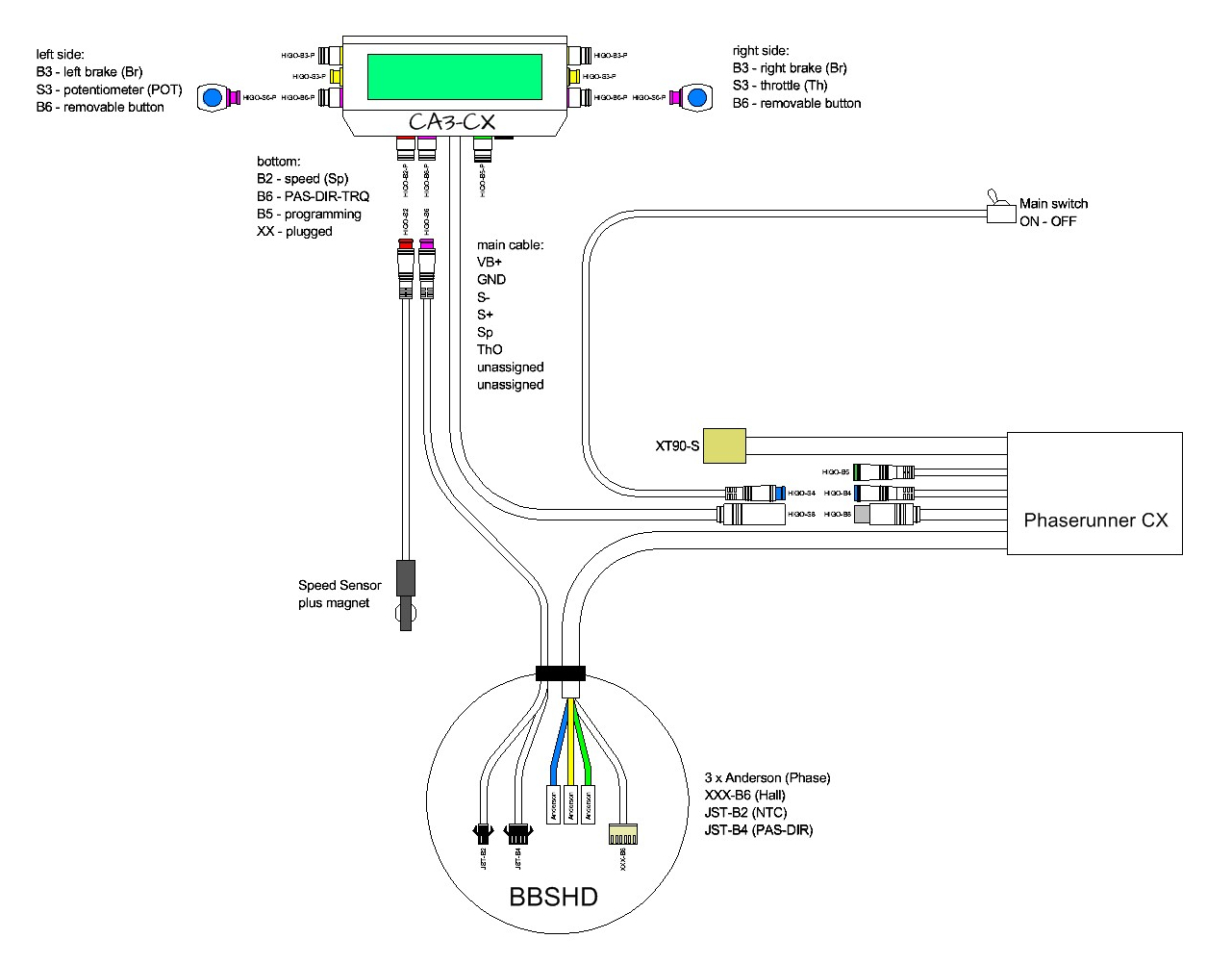
A higher resolution (scalable) version of this photo is in this PDF file. This provides a complete guide all power and signal wires needed to operate the system.
Return to Top of Page Return to Main Menu
Generally we connect all of our throttle inputs (manual and PAS/Torque) to the CA to take advantage of its throttle control features. This is opposed to connecting the manual throttle directly to the (typical for Infineon) Red/Black/Green wires of the motor controller. The wiring convention for the CA throttle connector is a JST-SM 3 wire, with the throttle side being the male pins.
There are some "limit" settings for the throttle, including legal, safety, and performance considerations. To minimize issues with running into two different limits that are trying to do the same thing, leave settings at the default or maximum unless necessary.
Return to Top of Page Return to Main Menu
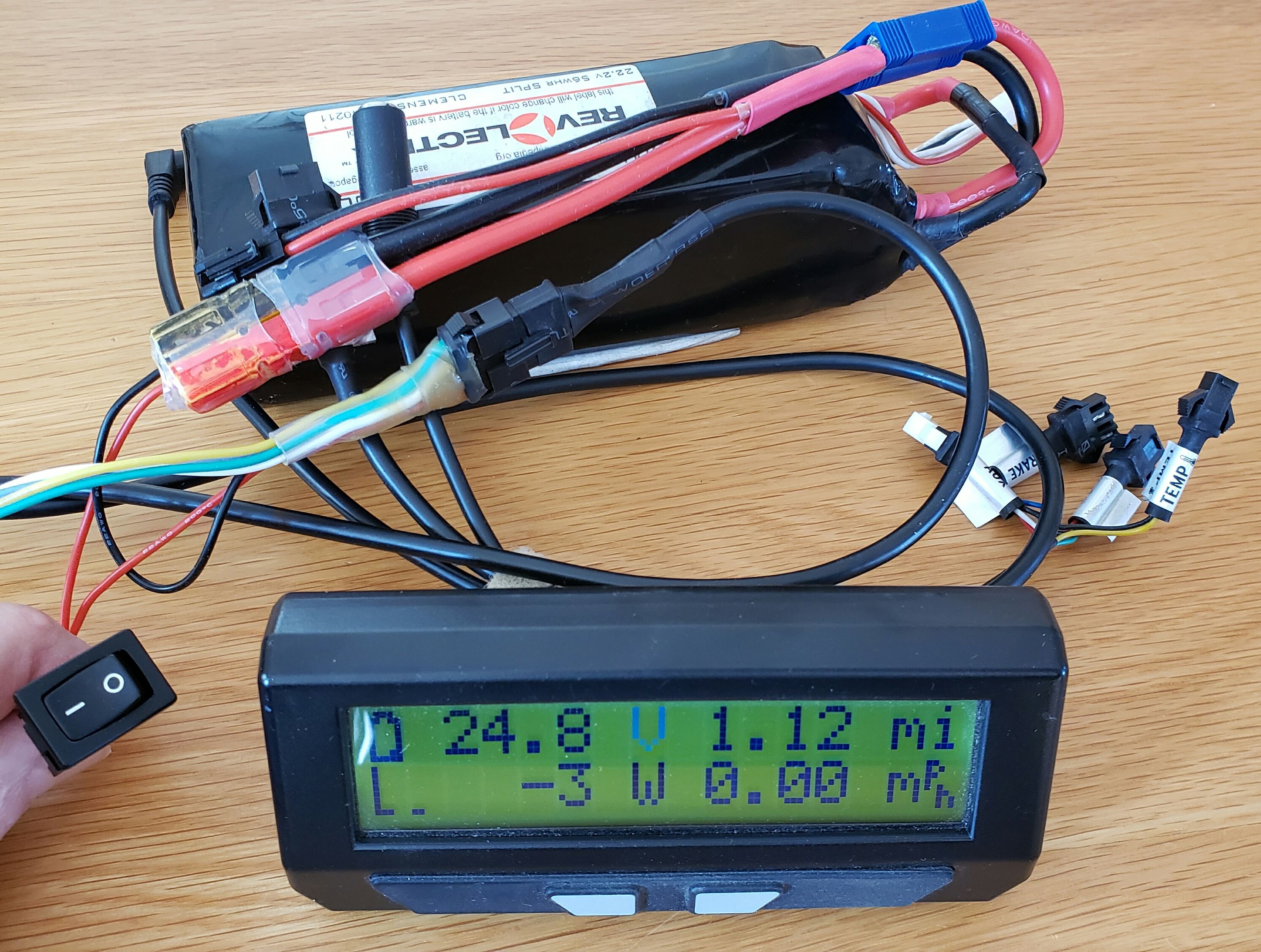
I frequently want to be able to review or change program settings on a CAv3 without having to be near the vehicle on which it's used. This is especially true here in Minnesota when the vehicle is parked in a cold garage and you'd rather do the work where it's warmer. You do not need any controller in the circuit to program the CAv3, nor the motor, nor the bike's traction battery for that matter. I made a very simple cable/plug/adapter/switch assembly using an 8 year old 6S/22V lipo battery, an inline SPST switch, and a JST-SM6 plug to mate with the CAv3's CA-DP plug. Ideally the battery you use would be close to the bike's voltage, but it's not necessary as long as it's high enough to run the CA, which I think could be as low as 12V. Note the greyed out "V" on the CA display in the photo below, which indicates a low voltage cutoff (LVC) condition. This is due to the fact that I have the CA programmed to work with a 14S/52V traction pack and am using a 40 volt LVC setting, well above my kit's 6S/22V battery. So even though this setup won't drive a motor with these settings, it works fine for programming the CA. The actual voltage you'd be using is more important if you are also testing other inputs to the CA and need accurate watts/power readings.
You can ignore all but the DC traction pack voltage (red and black) wires in the JST-SM6 DP plug, and put the on/off switch inline with the red/positive DC lead. I brought out all six of the DP plug wires in my kit because I occasionally run tests using the CA with other inputs, so I wanted ready access to the shunt and speed wires.
Photo of DIY adapter kit