This page's link: "erowbike.com/troubleshooting"
Return to Main Menu
Troubleshooting
| Troubleshooting Resources |
| eBike Tester |
Typically the first step in diagnosing issues with the motor, controller, and throttle. |
| Wiring & Connector Issues |
Experience shows that this is the most common failure encountered by LEVs. |
| EMI/RFI ("noise") |
Diagnosing and fixing issues surrounding corrupted data signals. |
| Controller Repair |
Diagnosing and fixing issues surrounding BLDC controllers. |
| Troubleshooting @Grin |
The web's BEST single point resource when your LEV project needs some TLC. Brought to you by the world's best ebike shop, GRIN Technologies at ebikes.ca.
|
| Trailer Connections |
Didn't know where else to put this... |
eBike Tester
This handy $20 (or less, from china) white plastic box with lots of wires and connectors sticking out of it should be in the toolbox of everybody who encounters a DIY ebike. Similar testers available today will probably be delivered with english language labels. While everything this tester does could also be done with a digital multimeter ("DMM"), this tester makes it all a lot easier. One reason for this is that, if fitted with the right connectors, it is easier, faster, and safer to perform the necessary testing tasks. I got this unit from Edward Lyen back in the 20-teens. I've modified some of the connectors to mate with those in current use.
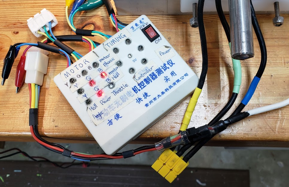 In this example, the motor's hall sensors were all functioning correctly, evidenced by their lighting up 3 LED's sequentially while the motor was rotated by hand (only the green/"G" and blue/"B" LEDs are shown lit in this still photo). The lower lit "G" LED is actually indicating that the tester's power is turned on, as is required for Hall testing.
Read thistester's manual created by Lyen and others for more details on its use. (PDF, 3 pps, 201?)
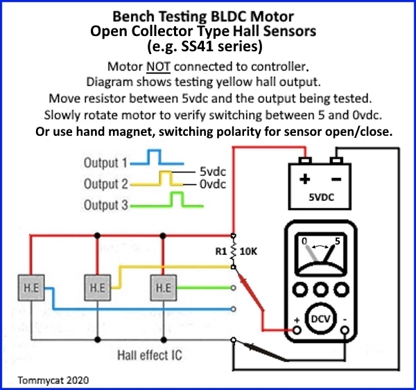
Hall Sensor testing
There are any number of ways to determine whether the Hall sensors embedded in a BLDC motor are working correctly. One of the easiest is the use of an "ebike tester", as shown above. Shown below is another way to test Hall sensors. Note that Hall Effect sensors typically used in the eBike world are 'latching' sensors. To change state between ON/OFF, they must 'see' alternating north/south magnet polarities. Check the data sheet for the particular Hall sensor being used, but typically a north magnetic pole presented at the front (side with the label) of the sensor will latch it in its ON/high state, at approximately 4.2 volts.
If you just have a DMM and want to test Hall sensors, read Grin's wonderful PDF instructions on how to do that. (PDF, 4 pps, 201?)
Wiring & Connector Issues
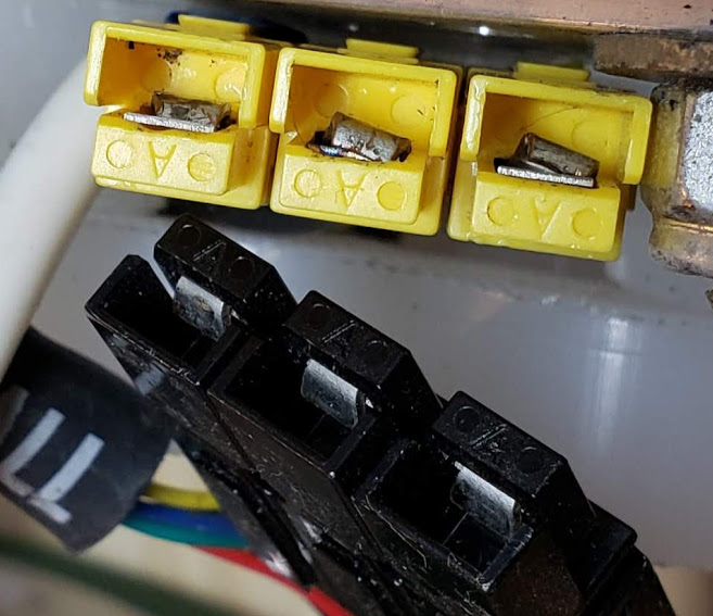
One of the most common connectors used in the LEV world for power wires/cables is the Anderson PowerPole (R) ("Anderson") connector. In the lighter weight series (15-45 amps), these connectors are very convenient and flexible in their use, and are generally reliable - if used correctly. Incorrect crimping or other mechanical failures are an extremely common cause for circuit failures, resulting in a vehicle not working or going up in flames.
Shown below is an example of how these Anderson connectors can fail (the three yellow connectors). The black connectors show the correctly positioned inner terminals.
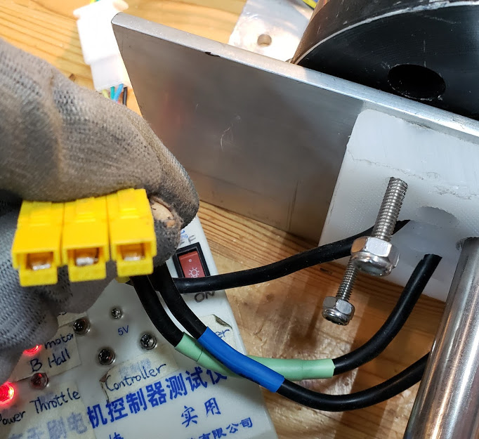
The same yellow connectors shown above now have the cable terminals repaired and correctly installed into the Anderson housings. Note that the 'hooks' of the terminals crimped onto the cables, and inserted into the housings, are inserted so that they're completely over the top of the housings'spring plate. When inserting the terminal into the housing, keep pushing until you hear a distinctive 'click' generated by the terminal slipping over the spring.
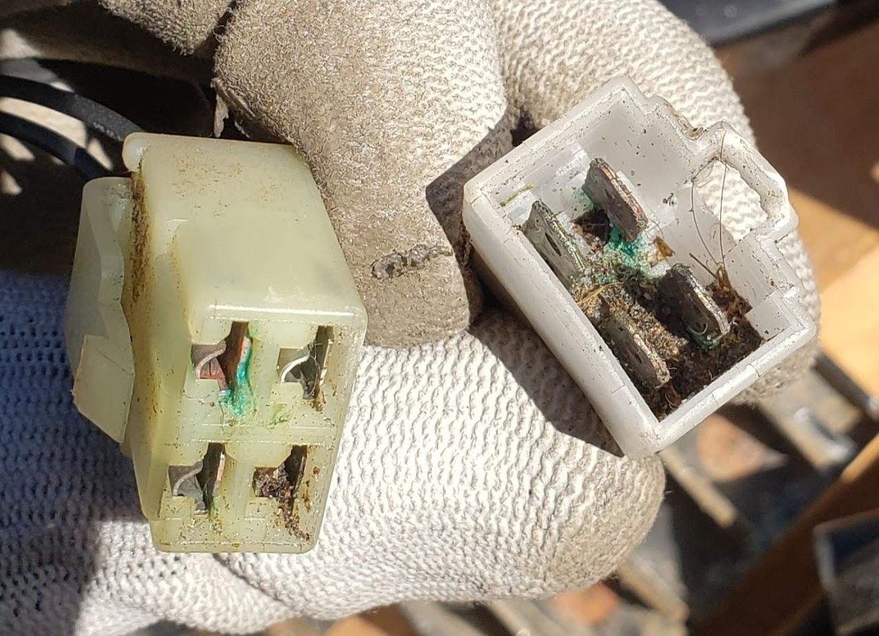
The next photo shows the other common cause leading a circuit failure -- damage from a harsh environment. This wiring connector, used on a mobility scooter, accumulated organic matter (dirt) over several years of outdoor use. Fairly harmless when dry, the organic matter coupled with moisture led to corrosion on one of the terminals and a low-level short between two other terminals. Two of the four wires in this connector failed to carry the correct amount of current and led to the scooter's control board reporting an error with the electric brake. This effectively immobilized the entire scooter, even though the actual brake and other drive parts were still fully functional. A design which would have protected this connector from the elements, or the use of a connector designed for such use would have prevented this scooter's failure.
EMI/RFI
Both electro-mechanical interference ("EMI") and radio-frequency interference ("RFI") can be pernicious gremlins that will completely kill an otherwise perfectly functioning LEV.
We originally ran into this issue when implementing our strain gage based methods used to provide electric assistance and control for LEVs, including the INA circuit board.
In this example from the Endless-Sphere forum, one member describes how a very specific type of EMI (current induced into the bike's steel frame from a running motor) prevented his bottom-bracket based torque and cadence sensor's data from being accurately read.
Although he does not specifically identify the motor as the primary cause, in our experience it is the actual spinning motor, solidly attached to the bike's frame, which is the actual culprit.
Trailer Connections
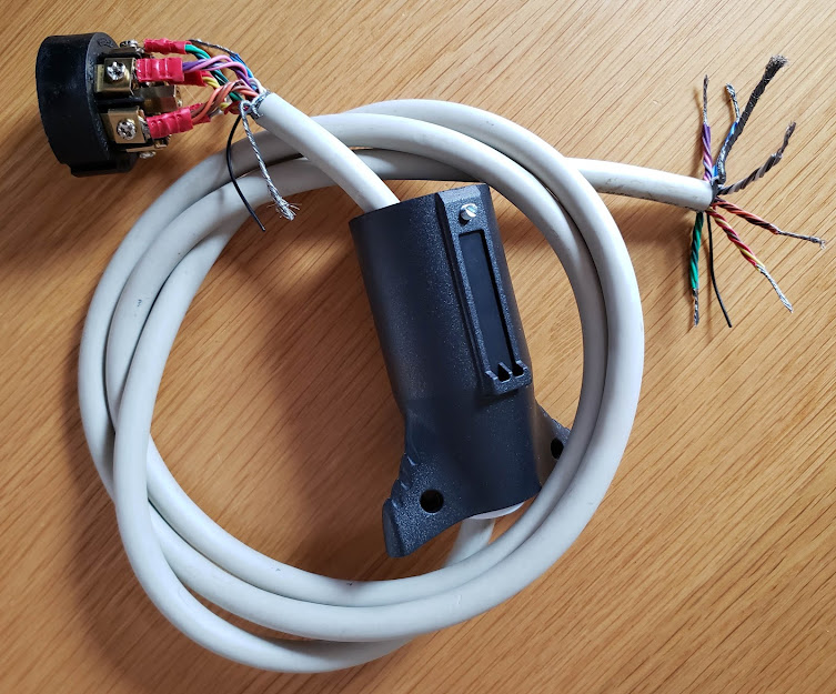
The following table shows the inter-plug connections used for lighting the DIY ebike carrier I made in 2021 (originally for the Subaru). It is now (2022) used with Yves, the Tesla Model Y, which uses a standard North American "Pollock" 7 pin round plug, installed at the factory. The LED lightbar (superbrightleds.com) on the bike rack presents a 5 pin male "aircraft style" round plug that I provided. I've made a 48" connecting cable from an old 25 conductor cable used to connect a parallel printer back in the 1980's. I cut off the ends (one Centronics male and one DB-25M), leaving 25 x 26AWG stranded conductors, plus a chassis ground and a webbed wire shield. Since I only needed five conductors for the light bar on the bike carrier, I bundled groups of wires together to come up with greater current carrying capacity. I ended up with 6 (5 plus a spare) bundles consisting of 4 wires each, with one data conductor left over. (I should have added that wire to the GROUND bundle.) Note that the colors in the column below do NOT follow a single absolute standard. The auto industry follows several different conventions and there is no guarantee that a particular manufacturer will provide a socket that adheres to any particular standard.
| Pin # - 7 Pin Plug |
Function |
Color |
Pin # - 5 Pin Plug |
Notes |
| 1 |
GROUND |
Brown |
1 |
SAE says White wire; likely to carry the most current. |
| 2 |
Electric Brakes |
Blue (SAE) |
N/C |
Proportional/analog voltage |
| 3 |
Tail/Running Lights |
White |
2 |
SAE says Brown; |
| 4 |
Aux. 12VDC |
Red/Black (SAE) |
N/C |
Used for trailer charging, etc. |
| 5 |
Left+Stop |
yeLlow (SAE) |
3 |
|
| 6 |
Right+Stop |
gReen (SAE) |
4 |
|
| 7 |
Reverse/Backup |
Blue |
5 |
Center stud on 7 pin plug; SAE says Violet; |
The combination of four 26AWG wires results in an equivalent 20AWG conductor. Even with normal PVC insulation and a cable run of less than 4 feet, this can easily carry 10 amps at 12 volts DC, which is more than enough for my LED light bar.
This shows the cable with 6 x 4 conductors bundled, before the final plug assembly. The ends going to the 5 pin connector will be soldered into cup-style terminals and protected with heatshrink tubing.
Return to Top of Page
Return to Main Menu