| Table of Contents | |
|---|---|
| Abstract/Rant | WARNING: Don't read this if you don't believe in science, since it will only aggravate you! Return to Main Menu |
| To Solar or Not To Solar? | The very first question to answer for any solar installation. |
| To Grid or Not To Grid? | The second question to answer for any solar installation. |
| The AC-DC House | Nikola Tesla or Thomas Edison or both? |
| 50 Watt Array: 10 watt @ 1S5P | My first organized effort to produce and quantify electrical energy for personal use. |
| Solar charging supercapacitors | Storing solar panel output in something other than batteries. |
| 1,035 (1kW) Watt Array: 345 watt @ 1S3P | This array is the first set of 'full size' solar panels to test the scaling effect. Is it as simple as just moving the decimal point? |
| Solar charging lithium batteries | This is a much more common use case for solar panel output. |
| 3.33kW Watt Array: 370 watt @ 9 Bifacial Panels | This will be a multi-year project to design a relatively small, but 'commercial grade' solar panel array to generate the electrical energy for an electric car. |
| Solar Energy Measurements | What we are doing to determine how much energy we are actually able to harvest from our solar panels. |
| Solar Dump Load | A loosely used generic term for any device used to consume 'excess' solar energy. A solution to a 'high class problem.' |
WARNING: Don't read this if you don't believe in science, since it will only aggravate you! Return to Main Menu
< r a n t >I started putting up solar panels in 2016 simply to experiment with the technology and to learn from my efforts. Just based on personal experience and observing the world around us, I've known at least since the 1960's that burning fossil fuels to obtain energy was not a good idea in the long run. Maybe it was OK for a while if I didn't blatantly waste it, and found cleaner and more efficient ways of burning it. But by the 1980's it was already perfectly obvious to anyone who cared to think about it that burning fossil fuels was not only a bad idea, but that it would have extremely dangerous consequences. This was true even if I was to use fossil fuels "responsibly," which clearly I was not. I could be worse(Insert "rolling coal" emoji here), but I could and hope to be better.
The efforts documented here are not motivated necessarily by trying to "be green" or to save the world, but by trying to improve the odds of my own survival, and of those I care about. I've encountered numerous 'wake-up calls' over the years, including the 1970's gas shortage, that tell me that it's important to pick the right horse when it comes to energy dependence. Our US government, led by both Republicans and Democrats, have admitted that dependence on (foreign) oil is a national security risk. Additionally, the Democrats understand that burning any fossil fuels, regardless of their source, poses a myriad of additional risks, including undesired climate changes and dangers to our physical health. At some point in the future, all of this will be so obvious that even the Republican leaders will be forced to admit that this is going on, in spite of an apparent continuing (this is being written in early 2022) desire to make stupidity a desireable quality. But even when that time comes, our government still won't be competent enough to get the necessary things done in a timely fashion. This will be true even if it is shamed into really trying by the likes of Al Gore and Greta Tintin Eleonora Ernman Thunberg.
Fortunately, we can get started without waiting for the government to do a thing -- other than to get and stay out of our way. If "the government" can't do the "right" thing, they should at the very least stop doing the "wrong" thing, such as subsidizing the continued misuse of fossil fuels. First, do no harm.
If you don't think that a single individual can in a few short years significantly move the sustainable energy needle in the right direction, simply google the terms "Elon Musk" and "Tesla." We don't need subsidies, we don't need tax breaks, we simply need a level playing field and a significant minority of individuals willing to do the right thing, in whatever capacity they can.
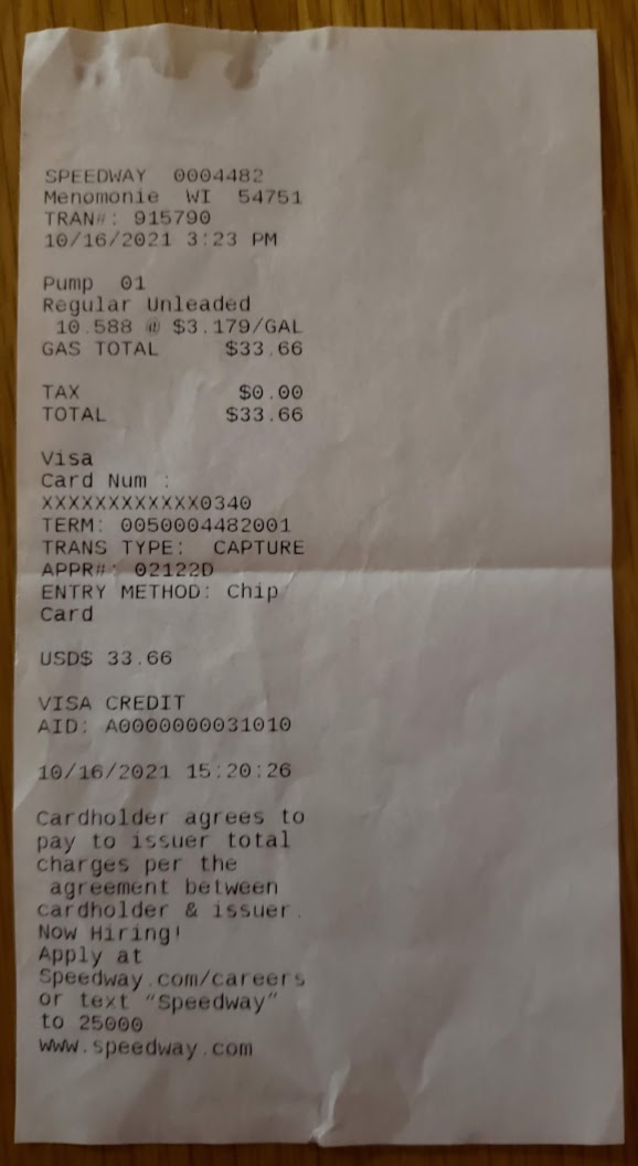
For me the first step, documented below, was reaching the goal to never buy gasoline again. As of Fall 2021, our household has gotten rid of all devices that use gasoline, including a 21 year old car, a lawnmower, and a chain saw. The car has been replaced with a new battery-electric vehicle (BEV), the lawnmower by a dumpster-dive model re-purposed to be powered by ebike batteries, and the chainsaw by an electric model. The complement to this goal is to produce on-site the fuel these new items use by converting some of the sun shining on us into electricity.
... and this is why energy dependence on solar is a good strategy.
Receipt for the last gasoline I intend to purchase in my life. What's the date on your receipt?
Return to Top of Page Return to Main Menu
The very first question you need to answer when considering the installation of any solar panels is whether or not it meets any of your goals or expectations. Only you can know what your goals and expectations are. From saving a few bucks to saving the world, the possibilities are endless. Installing your own solar panels (vs investing in somebody else's) may or may not meet your goals and expectations, and if not, don't do it. If you have money burning a hole in your pocket and you just want to invest it wisely and still save the world, buy TSLA stock instead.
If the answer is "yes," then you will need to do math. Lots of it. Most of the math required isn't particular difficult (probably no algebra or calculus), but it will be somewhat tedious. If you choose to go with a commercial installation, you can probably elect to let the installer do everything, but you'll risk that you might not get exactly what you had hoped for. Like buying anything, Dick Cavett Emptor. Even with incentives (government tax breaks, etc.) and falling prices for solar hardware, it ain't gonna be cheap. I got a great deal for some 'fire sale' 370 watt solar panels (10 for $170 each), and even if I ignore my own labor, miscellaneous mounting hardware and electrical supplies, these panels will have to generate 12,143 kWhrs of electricity (at $0.14 per kWhr) just to pay for themselves. In theory, these ten panels could generate 3.7 kWhrs of electricity in one hour of full sunshine. Continuing this line of reasoning, it would require 3,281 hours of ideal sunshine to break even. Assuming (optimistically) that one could get three such hours per day, it would still take 1,094 days (three years) to get there. These back-of-the-napkin calculations don't include the tax breaks that effectively lower the purchase price, but they also don't include the wiring, mounting hardware, junction boxes, switches, and miscellaneous items needed to get these panels to produce any electricity at all. Most importantly, these calculations don't include either the MPPT controllers or the batteries needed to get the most electricity from the panels and do something useful with it. The items in these last two hardware categories could easily cost ten times the price of the panels, and would dramatically lengthen the pay-back period for the solar installation.
In my solar venture (described herein), I decided to install some solar panels just to see how it goes. I try to avoid making unnecessary decisions and have a non-committal relationship with math, both of which traits heavily influence this ongoing solar installation process. My goal is to learn as much as I can while spending as little money as possible, and the only expectation I have is some peace of mind resulting from a degree of energy independence. If ultimately successful, I might have some bragging rights and get something for nothing.
Return to Top of Page Return to Main Menu
If you do decide to go solar, the very next question you need to answer whether or not the solar panels will ever be connected to "the grid" -- the local power company that supplies your electrical energy.
If the answer is "yes," then you will need to satisfy numerous requirements that have little or nothing to do with solar energy. These include the permitting process, zoning laws, rules relating to your local electric utility, and who knows what else, depending on where you are in the world. Your system will be described as "grid tied," and all equipment you use for the installation will have to have various UL listings and/or certifications (at least if you live in the USA). Note that most solar equipment such as inverters and micro inverters are built to automatically and instantly disconnect (disable) your solar panels when the grid is down. This means, that by default, when the grid is down, so are you -- even if the sun is shining brightly. The term anti-islanding is frequently used in this context. The most commonly stated reason for this mandatory disconnect is the safety of people working on the powerlines. In 'real life' no competent utility worker would ever work on any electric lines without making sure it's safe to do so, using techniques such as grounding the lines, etc. If necessary, they would treat the lines as 'live' and proceed under those conditions. Would you work with sticks of dynamite which any random stranger could detonate at any time? On the other hand, I think that where safety is concerned, it's better to err on the side of too much vs. too little, so add layers of safety wherever it's reasonable to do so.
If (and this turns out to be a big "IF") you want your solar panels to keep producing energy when the grid is down, you need a "hybrid" inverter with a "transfer switch" and some form of storage battery. The transfer switch will automatically disconnect the grid from your solar panels, and the battery will work with the hybrid inverter to keep your solar panels producing energy. As for powering your house, you'll also need to have a "critical load panel" which feeds things like your refrigerator, selected lights, and maybe your furnace fan. This critical load panel will be connected to your hybrid inverter. When the transfer switch disconnects the grid during a power outage, the hybrid inverter and the battery will supply power to the critical load panel. If you're willing and able to install enough solar panels, a hybrid inverter with enough power (kW) capacity, and a battery backup system big enough (kWhrs) to accommodate your needs, your critical load panel can be your regular house load panel. Under these circumstances, when the grid goes down, you might not even notice it since your transfer switch will in a matter of a few milliseconds connect you to your backup system.
If the answer to the grid-tied question is "no", you likely won't have to deal with all the paperwork and other complexities associated with the solar installation outlined above. You'll need to decide what you want to use your solar energy for, and then design and install a system that meets your needs. This is the direction we're going in here, and all of the projects below assume that there will be no connection to "the grid". We're hoping the first sentence in this paragraph is actually true.
Return to Top of Page Return to Main Menu
Most typical houses in the 21st century obtain their electrical energy from "the grid" in the form of alternating current ("AC"). Voltages ("V") will depend on where in the world the house is located, with North American houses being supplied with two independent phases of 120VAC each, allowing for devices to run on either 120VAC or 240VAC, if both phases are used for the same device. For devices that operate on various direct current ("DC") voltages (electronics like computers), there will be an inverter type power supply used to change the grid supplied AC into whatever DC voltage(s) the device uses internally. These inverter power supplies not only invert ("rectify") the AC current into DC, they also change the voltage from 120V to the typical 5V, 9V, 12V, 19V and other miscellaneous DC voltages that the electronic devices actually use internally. While not advertised, nor likely even approved, for use with comparably high input DC voltages (instead of AC), these inverter power supplies frequently are capable of doing their jobs with either type of supply current.
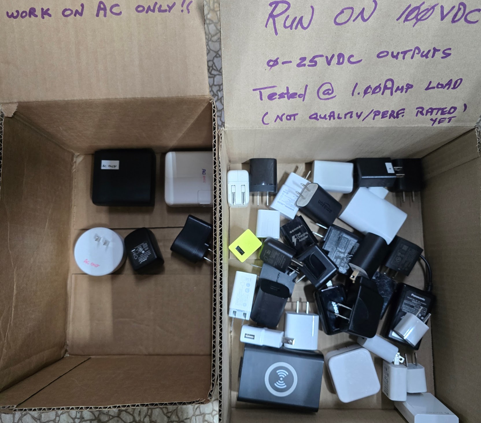
From a random 'bucket full' of USB power supplies meant to be plugged into 120VAC (grid) outlets, the ones in the right cardboard box work just as well when plugged into a 100VDC (two 100AHr 51.2VDC LFP batteries in series) source. This ratio also seems to hold true for the in-line 'wall wart' inverter power supplies of varied output voltages. This means that I'm moving ahead with switching over to a "100VDC house voltage" for all of our electronic devices, powered by a bank of LFP batteries, which in turn are kept charged by several arrays of solar panels. Our goal is to have a house-wide "UPS" system that's completely off-grid, except for backup charging from the grid for extended cloudy days. I'm still running the numbers as to balancing the number of solar panels with the amount of battery storage to never having to fail over to grid charging. Because the solar supply is not predictable, you need to have either too many solar panels or too much battery capacity -- or both. With very clever management you can minimize this un-balance, but most likely you reach a point of diminishing returns before achieving a perfect balance. "It's a journey" -- if cliches are permitted.
In the meantime, if there is a long stretch of cloudy days, AND the grid goes down, the cybertruck will automatically (after a 30 second or so switching delay) make about 123kWHrs of electricity (120/240VAC) available to our house's electrical system, some of which can then be used to re-charge the DC 'house' batteries. The cybertruck makes this possible via a PowerShare (tm) system ($2K hardware/software plus installation, 2024 pricing), which enables bi-directional vehicle-to-home ("V2H") connectivity. The cybertruck also has built-in (no extra equipment needed) vehicle-to-load ("V2L") 120/240VAC outlets.
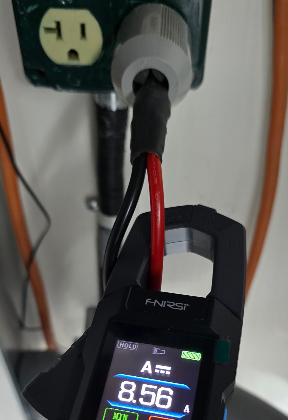
These 'true 20 amp' receptacles in an earlier life supplied 120VAC for powering AC tools in the garage. Now they are located near the 'high voltage battery farm' and make handy outlets to allow the quick dumping of excess energy coming from the solar panels. Here a modified 850 watt portable electric (resistance) heater is plugged into the now DC outlets. It's February in Minnesota, so the 'waste heat' is quite welcome at this point. Note that the clamp-on ammeter is showing 8.56 amps of DC current passing through the red (positive) cable.
This shows the heater mentioned above. The modification was to remove the factory original fan which required AC for its operation and to replace it with a DC fan. I repurposed a small fan originally used for cooling an electronic device, and powered the fan via a 'wall wart' also repurposed from having powered a now-obsolete electronic device. This particular wall wart will begin to produce its nominal output of 12?VDC at about 25VDC input, so the fan will already be spinning before the heating coils become really hot, helping extend the life of the heater.

Return to Top of Page Return to Main Menu
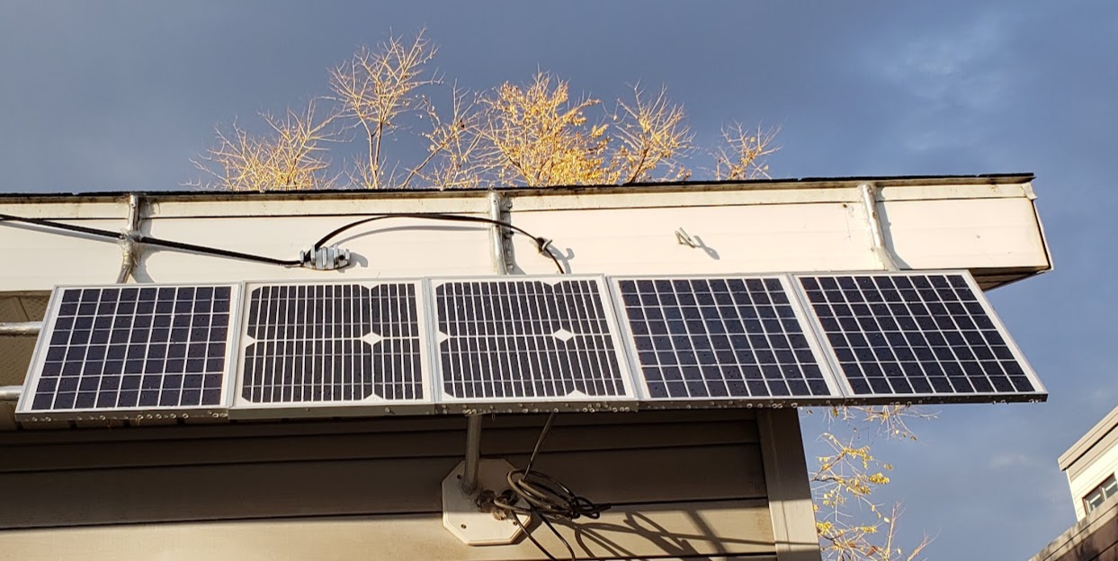
This five panel array is was mounted on the detached garage roof, facing directly south. The panel outputs are connected in parallel (1S5P), but only after each panel's individual output is measured and recorded. The vertical angle is fairly steep, both to favor the low winter sun and to help keep snow off the panels. The only shading for these panels happens in the mornings when the sun is blocked by the four-story commercial building to east (right side of photo).
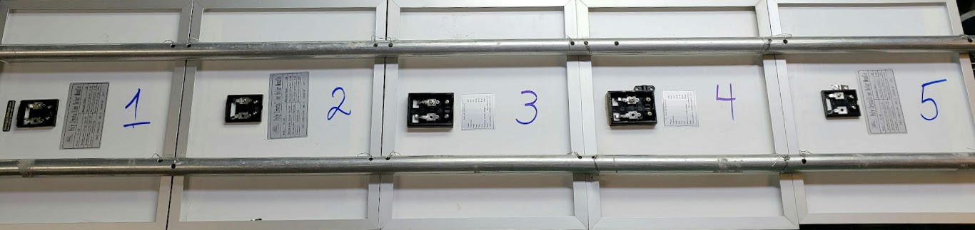
Showing rear view; when mounted on roof, panel #1 is to the far right (East). Panels 1,2, and 5 are of the "Poly Crystalline" type, while panels 3 and 4 are not labeled as to type (are they mono crystalline?).
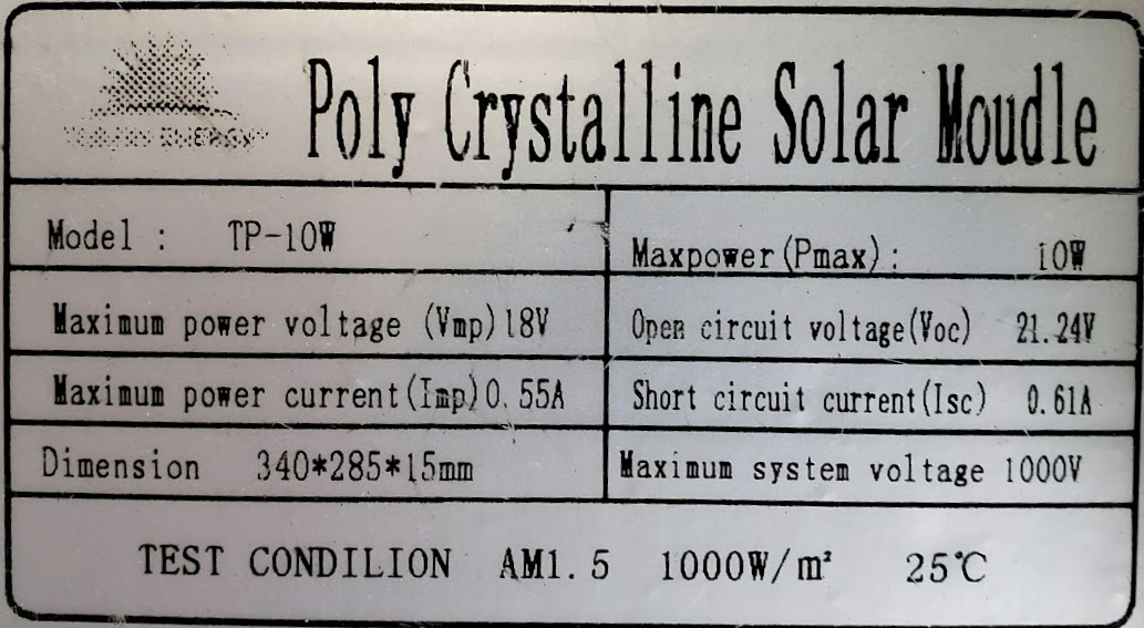
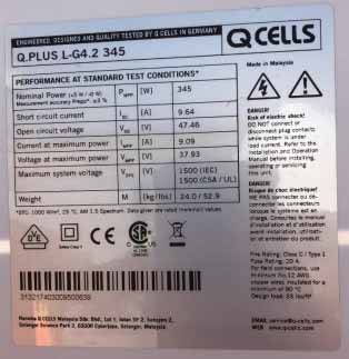
The factory specifications for the two types of solar panels used in this array are almost identical. The following shows two decals attached to the back of two of the panels. These give the 'stats' for the panels, which is very typical for all commercially available solar panels. For definitions and explanations of all these properties and values, see the very thorough wikipedia entry Solar panel. This will explain why these panels are called "12 volt panels" even though the label has two voltage values of 18 and 21.6 volts.
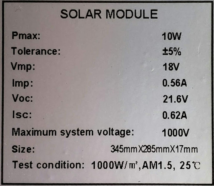
Note the 'chinglish' language ("Moudle", "CONDILION") used by this Chinese manufacturer.
These 'no-name' panels have actually been performing extremely well, and their power output ratings may even be on the conservative side (see graphs showing a sample one-week output below). Panel 1 (green line) had a max power output of nearly 18.5 watts, well above its 10 watt rating.
The output of each 10 watt panel in the array is individually measured and recorded before being combined with the other four outputs and sent to the 12VDC "battery farm" for use and storage. The following graph shows the array's output for one week, April 4-11, 2022. Each panel's VOLTAGE in the top series, and POWER (in "watts", which is voltage x amps) in the bottom series. The X scale is time, while the Y scale is the amount being measured. Each panel's output is represented by a different color. This graph screenshot was taken at 9:30AM on 11 April 2022, so all of the panels were still in the shadow of the big building next door (to the East), so the *power* output is just beginning to rise even though the *voltage* of each panel has been near maximum for over an hour. Note that this (Grafana) graphing software's label uses "Current" not as "amps" but contemporaneous time, as in "now".
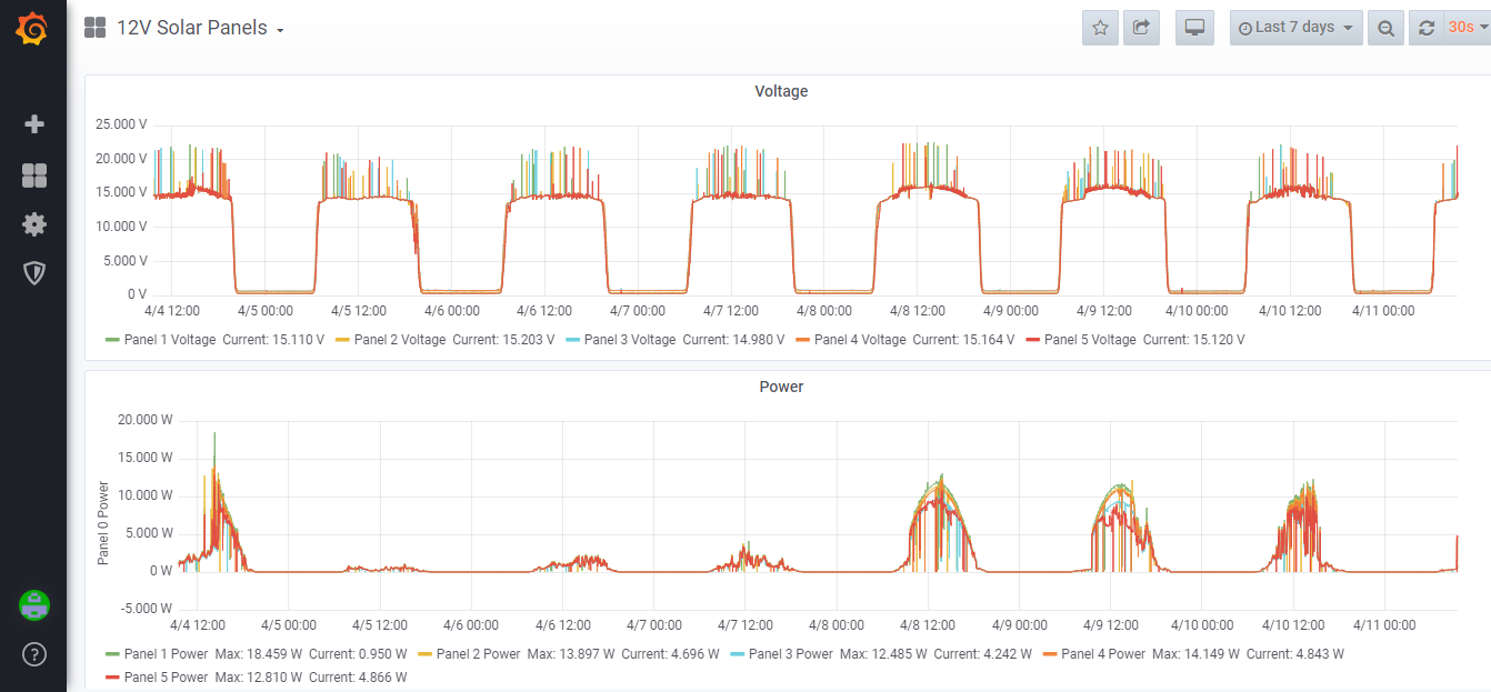
Looking at the graph, the takeaway is that for all practical purposes, the voltage output of a solar panel is irrelevant. On each day of the week shown, each panel's voltage output was consistently near the panel's nominal maximum limit during daylight hours. By contrast, each panel's power output varied widely by which day it was. April 5,6, and 7 were very cloudy/overcast days, and power output was very low (well below 5 watts). Looking only at the top (voltage) series, one would get the impression that the entire week was sunny, which it was not. Ultimately the only measurement that matters is the power coming from each panel. The maximum voltage output of the panel is only important when doing the wiring of all of the panels, for safety reasons.
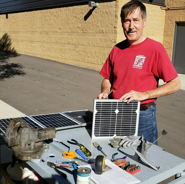
Starting assembly of the original five by 10-watt solar panel array in late 2018. These panels are un-branded factory samples and are provided courtesy of Bill James of JPods Inc., [jpods.com], thanks Bill! The 'nominal' power output of this array is a total of 50 watts (1/20th of a kilowatt/kW). This nominal output would be achieved under rather ideal standard testing conditions (STC). As it turns out, these five panels are rather unusual in that they still (in 2022) frequently produce more than 50 watts on a cold, clear, sunny day here in Minnesota, around 45 degrees of latitude.
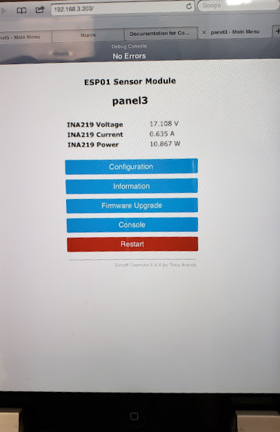
Each panel's output has been individually monitored 24/7 for the past several years, and has been recorded in a database. The panels' output is measured using a DIY combination of an INA219 instrumentation amplifier module and an ESP01 to transmit the data via WiFi to a linux server which records the data. Programs like Grafana help to display the data in a useful form.
A variety of displays, including this ancient iPad-1, are used to monitor the performance of the panels under varying conditions. The amount of solar energy captured by this small array is nearly inconsequential in the great scheme of things, but its teaching value is priceless.
The idea is for this small array to be the model for a larger array of 'full sized' solar panels of 300-400 watt capacity each.
Showing inside the garage near where the panels are mounted outdoors. This is early in the project and the connections are in the prototyping stage, with no monitoring in place yet.
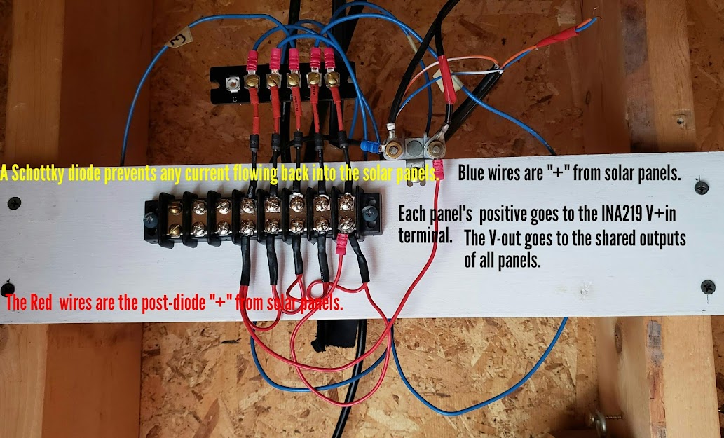
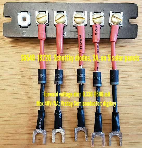
To prevent any current from 'back feeding' the solar panels, a diode is placed in series with each of the five solar panel's outputs.
Return to Top of Page Return to Main Menu
A solar panel is a great way to charge supercapacitors (a.k.a. ultracapacitors), as long as you are careful to not exceed the voltage rating of the supercaps. This arrangement is a wonderful way to learn the difference between the concepts of "energy" and "power." Power is the measure of how much energy can be delivered in a specific period of time.
Here one of the five 10 watt/12 volt panels from the array above is directly connected to a string of supercaps connected in series (to accommodate a higher total voltage). The little solar panel will slowly dribble "energy" into the supercap array until it's fully charged, at which point the supercap array contains enough "power" to start a big diesel engine in below freezing temperatures. However, since Tesla is producing Class 8 semi tractor trailor trucks as of December 2022, starting big diesels in any temperature will hopefully be a thing of the past.
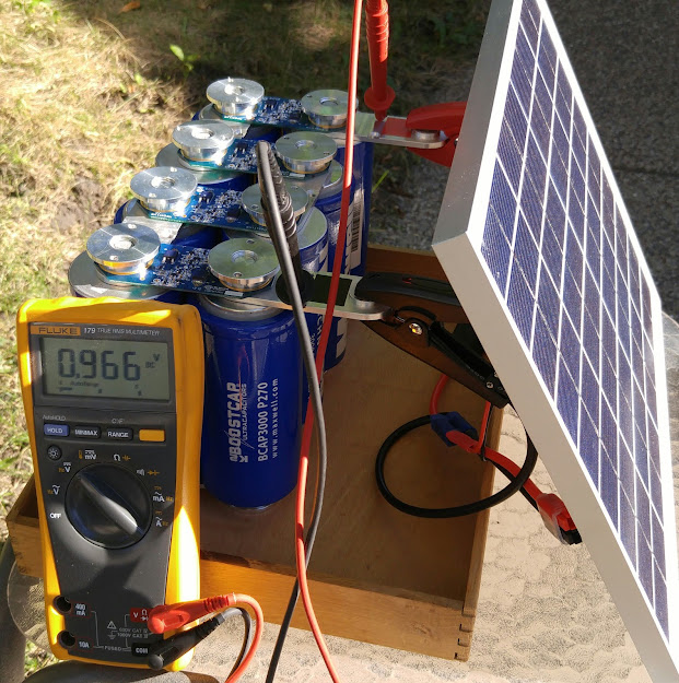
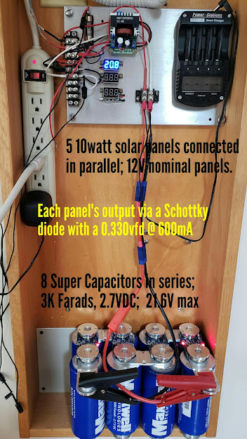
After sitting in bright sunshine for a while, the supercap array has risen from less than one volt to highest voltage this solar panel can muster, about 20.6 volts.x This is approximately 1 volt less than this panel's maximum (open-circuit) voltage. The array of eight supercapacitors is connected in series, so each capacitor's voltage limit of 2.7 volts is summed to allow the supercap array to be charged to an absolute maximum of 21.6 volts. These supercaps are very expensive compared to other discrete electronic devices, so even though they have a protective circuit to help avoid over-volting them, this is cutting it pretty close. Since they belong to JPods, I don't worry about smoking them [I don't really mean that, Bill!].
Leaving this setup out in the sunshine after this point will not result in more energy being stored because the solar panel can't push any more electrons into the supercaps since they are now at the same voltage as the solar panels. Should this be thought of as wasting energy?
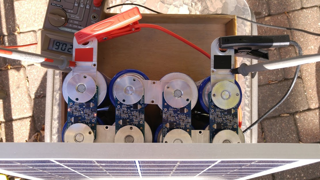
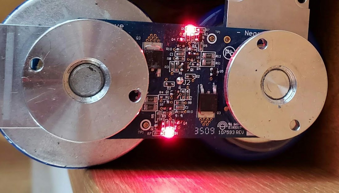
Here we see the supercap array being charged by the whole 5x10 solar panel array. Note that the panels and supercaps are at 20.8 volts, very near their maximums. If you look carefully, you can see the red LED's on the supercap's protective circuits showing that they are actively balancing the supercap array and dumping any excess current going to any individual supercap.
Closeup of the supercap's protective circuit at work:
Return to Top of Page Return to Main Menu
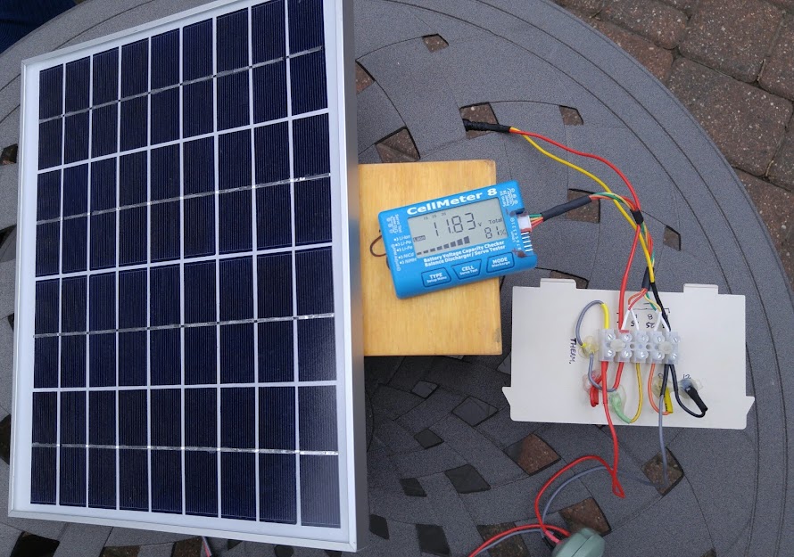
A solar panel is also a great way to charge lithium ion batteries. Here the same 10 watt panel is charging a lipo pack consisting of 6 18650 lipo cells connected in an 3S2P configuration. To prevent overcharging this pack, whose absolute maximum voltage is 12.6 volts (3 x 4.2 volts), a very small and cheap DC-to-DC converter is used (it's hidden in the small green pillbox at the bottom of the photo). The CellMeter 8 shown in the photo is a very useful meter which provides measurements including total pack voltage (shown as 11.83 in photo), percent of charge, each individual cell's voltage, and high/low cell voltages.
Here the 5x10 solar panel array is charging nickel-metal-hydride (NiMH) AAA "Eneloop" cells. These Panasonic rechargeable cells are very reliable and easy to use, and are considered an upgrade from the earlier generation of nickel-cadmium (NiCAD) rechargeable cells. I use these cells to power bright flashing LED lights on my helmet when I ride my bikes.
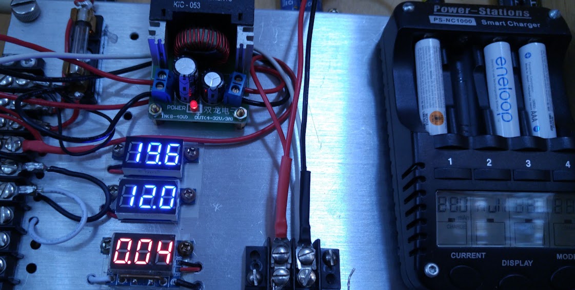
The cells are plugged into a 'charge controller' which takes the output of the solar panels (PV) and charges the inserted batteries until they are full, and then shuts off. Here we see a slightly larger DC-to-DC converter (with the red glowing LED) connected between the PV array and the charge controller to limit the voltage to 12VDC. It turns out that the charge controller's input circuitry was designed to handle the solar panels' voltage of up to 20 volts directly, so the converter is no longer used. The meters, from top to bottom, show the direct solar panel voltage (19.6VDC), the regulated voltage from the DC-to-DC converter (12.0VDC), and the current going into the charge controller in amps (0.04A). This could be stated as 40 milliamps, or about 1/2 watt of power. This means these batteries are probably fully charged, and the current flow is likely just powering the charge controller's LED display (barely visible beneath the "1 2 3 4" labels.
The following shows the solar panel array at its near-maximum open-circuit (Voc) of 21.6 volts directly connected to the battery charge controller labeled for a 12VDC input. Prior to doing this 'smoke test', I had opened up the charge controller and observed that the manufacturer of this "Smart Charger" had used input capacitors rated for 25V, so immediate smoke was unlikely. The input voltage is usually lower anyway when batteries are being charged because the load pulls down the panels' voltage. We now have a 12 volt battery pack that sits between the solar array and the AA/AAA battery charger, so it's no longer an issue. However, the same charger is still in use and working fine after several years of being operated over a 0 to 21 volt input range. Because it's being powered directly by solar panels, the voltage varies wildly between the two extremes. I did break off the negative terminal for the AAA battery holder in the #2 position, so I can only charge 3 AAA's at a time, but that was my fault, occurring while I was disassembling the case (and likely voiding the warranty).
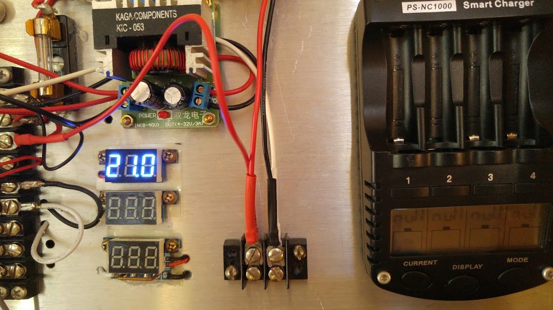
Photo of ...
Return to Top of Page Return to Main Menu
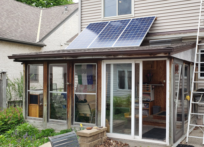
After assembling the tiny 50 watt array above, it was time to start experimenting with "real" (commercial grade), full-size, solar panels. These three 345 watt solar panels were sourced locally from "The Solar Panel Guy" who obtained them from a large scale solar 'farm' in Texas, where they had been briefly used. These 'recycled' 345 watt panels, referred to as "Q" panels, were originally designed by a German firm which was later acquired by Hanwah, a Chinese company. These three panels were originally installed on the porch roof in May of 2020.
... and showing the factory labels on the back of the panels.
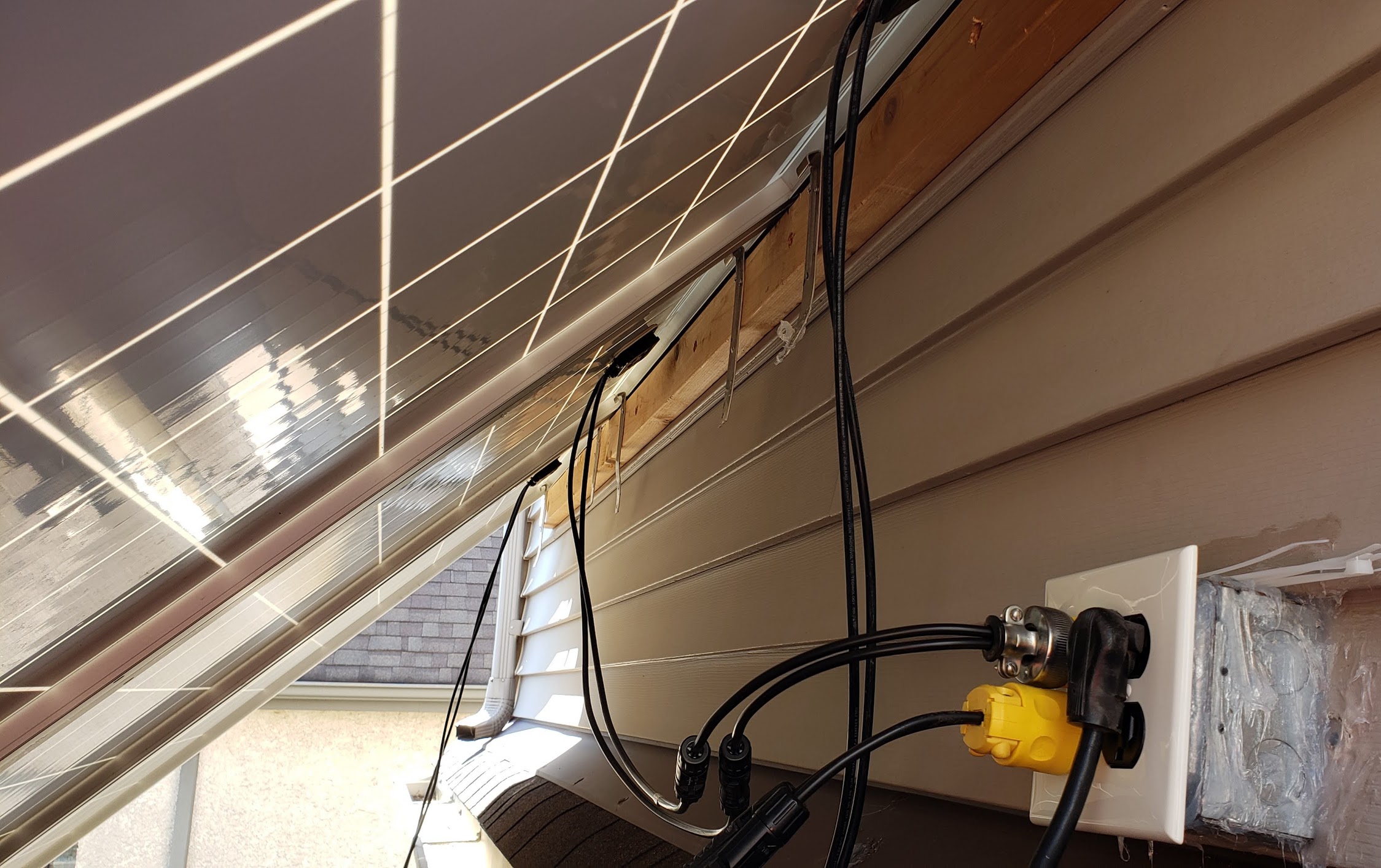
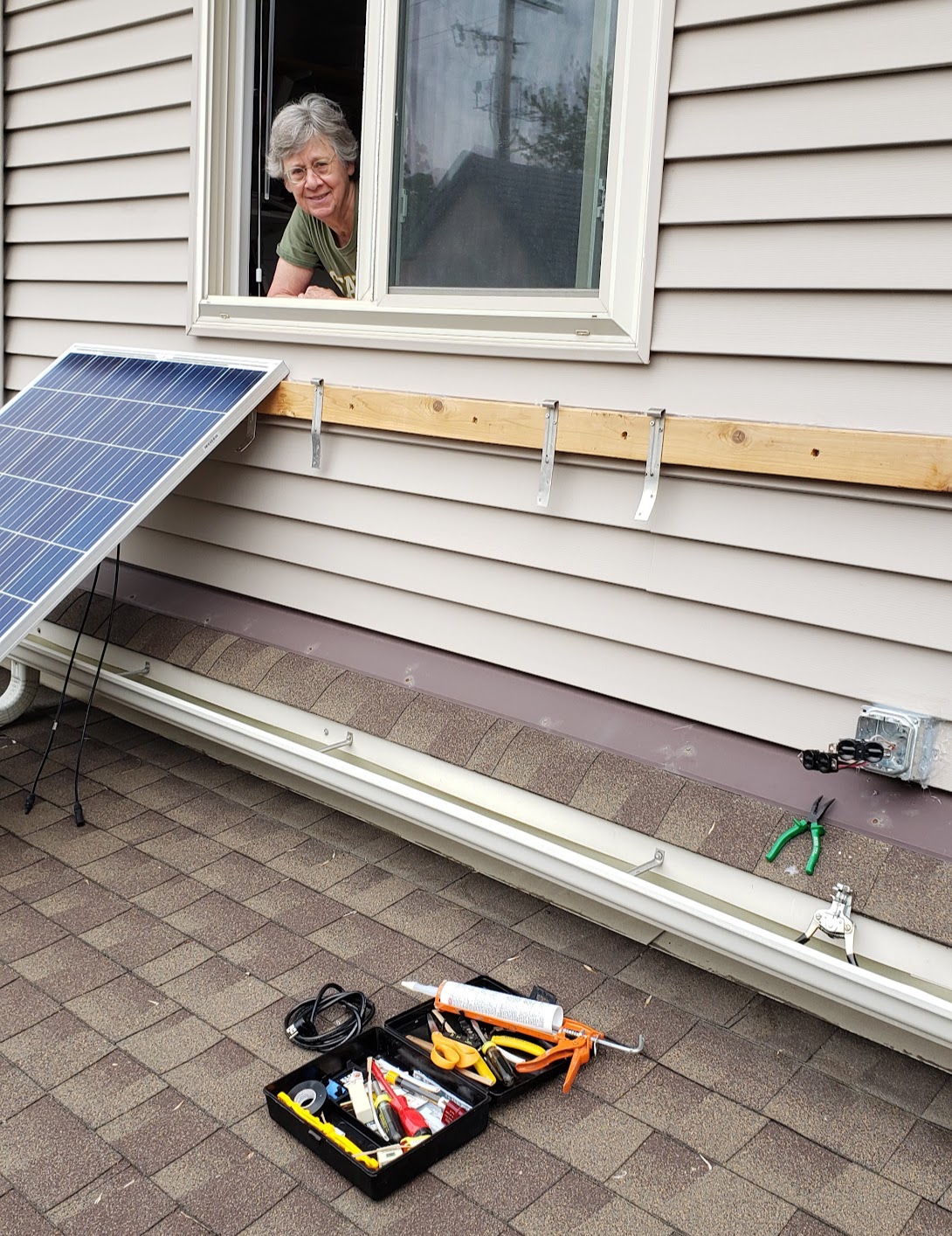
The following shows what NOT to do when installing panels. Using the miscellaneous 120VAC residential electrical boxes, plugs, and cords to connect to the panels violates every safety rule in the NEC and likely other sources as well. This temporary installation method, however, was extremely quick, cheap, and effective. The maximum current output of each panel is 9.64 amps at 47.46 volts DC, measured under short circuit conditions. The 12AWG copper wires, insulated for 600VAC, can easily (and safely) carry the amount of voltage and current involved.
View of the back side of the 3 panel array up on the porch. The wind could blow all three panels into the next county and the house wouldn't even blink. Six years on (2026) they're still in the same place, even after some fairly dramatic weather episodes. They'd do better in the winter if the bottoms weren't resting on the roof, since the snow doesn't completely slide off immediately. The snow factor is a real issue in northern regions, and the nine panels on the garage, which are mounted in an almost vertical position, simply don't have this problem.
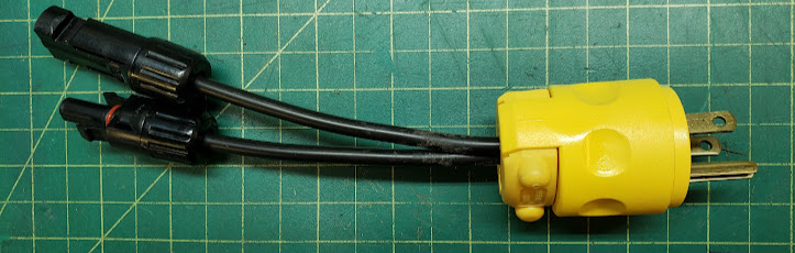
To make these solar panels very easy to disconnect from the electrical system, I made several of these plugs. They're known as "suicide plugs," for obvious reasons.
She's not approving this rogue installation by any means. She's just asking "Did you want fries with that?"
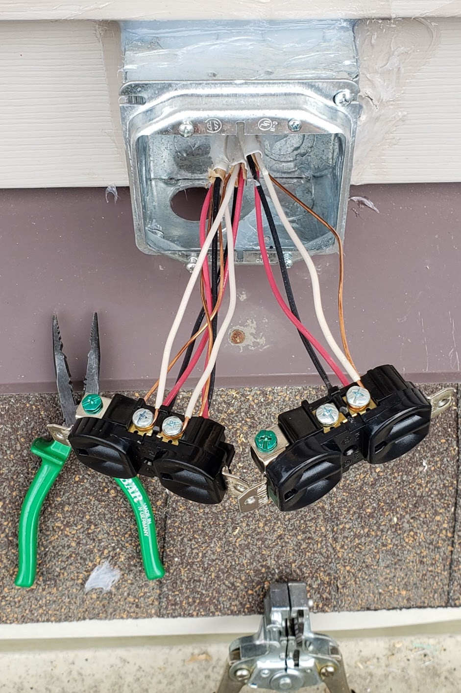
This shows the wiring details of the standard electrical box used. Each outlet of two duplex units is split into a single circuit, with wires of the 12-3 with ground romex doubled up. There is no accommodation made for earth grounding in the receptacles.
The combiner box for these three panels is in the basement computer room. It's a repurposed (dumpster dive) gray electrical panel box that didn't want to give up living with moving electrons.
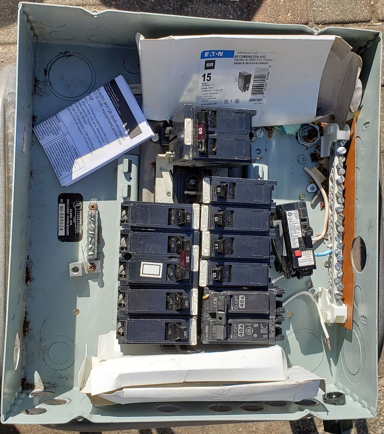
Removing the old AC circuit breakers and a bit of cleaning, and adding some DIY terminals made from old Western Electric telephone networking parts gives birth to a solar (DC) combiner box.
The next photo shows the three incoming 12-3 with ground romex wires from the three solar panels. This arrangement allows configuring the panels as desired without having to climb back up on the roof. Each romex cable has four 12AWG conductors, with the bare+white wires used for the Negative and the red+black wires used for the Positive conductors. This configuration reduces the effective voltage drop from the panels to this combiner box.
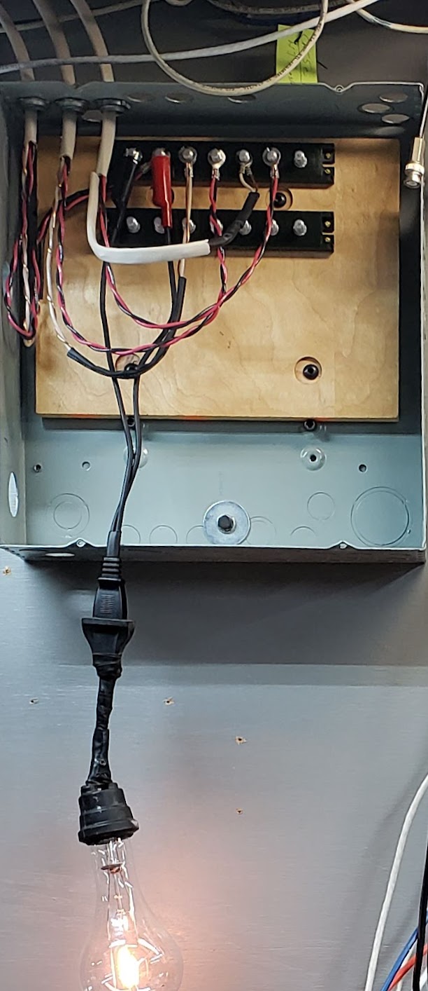
The photo below shows the addition of Schottky barrier diodes in the positive supply line from each panel. The negative (ground) lines are wired straight-through.
When all three panels are used in the 1S3P configuration, the total current will be below 30 amps (9.5A short circuit per panel) and the total voltage will be below 50 volts (47.5 OC voltage/panel). A reasonable MPPT controller to use for these three panels would be a 40A rated unit. Under ideal conditions, these panels might approach 1,035 watts (345x3), but would most often be supplying much less than this.
I have a bougerv 40 amp mppt solar controller, a collection of sla 12v batteries wired in parallel, and 3 345 watt Q solar panels to charge the 12v batteries. Should I connect the solar panels to the controller in parallel or in series?
Response from grok3 and grok4: Recommendation: Connect the Panels in SeriesThis is the better option for your setup, as it maximizes efficiency and minimizes losses without exceeding the controller's 150V limit. MPPT controllers like yours perform best with input voltages 1.5-3x the battery voltage (here, ~100V input vs. 12V battery is ideal). Overpaneling means you'll get closer to the full 600W input more often throughout the day.If shading is a concern (e.g., from trees or structures), switch to parallel-it's more resilient. Wiring Tips: Use MC4 connectors. For series, add a fuse or breaker rated for 15A per string (though only one string here). Ensure cables are UV-resistant and sized appropriately (voltage drop <3%). Safety Note: Always disconnect the panels before wiring. Confirm exact panel specs from your datasheet for Voc/Isc. If your location sees extreme cold (below -40°C), recheck Voc calculations. Controller Limits: No max PV input current is specified in the Bougerv specs, but series keeps it low (~10A), avoiding any potential issues. For parallel, the ~32A Isc is likely fine, as the controller only draws what it needs (up to ~18A for 600W at 34V).
Return to Top of Page Return to Main Menu
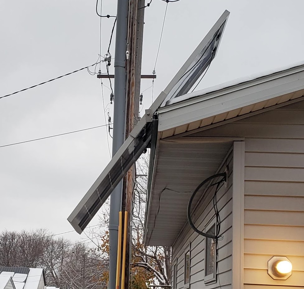
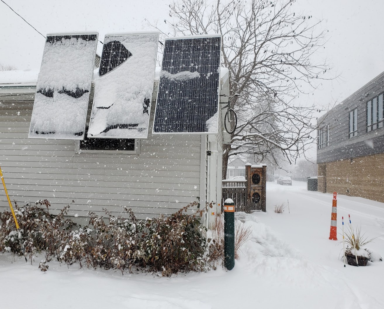
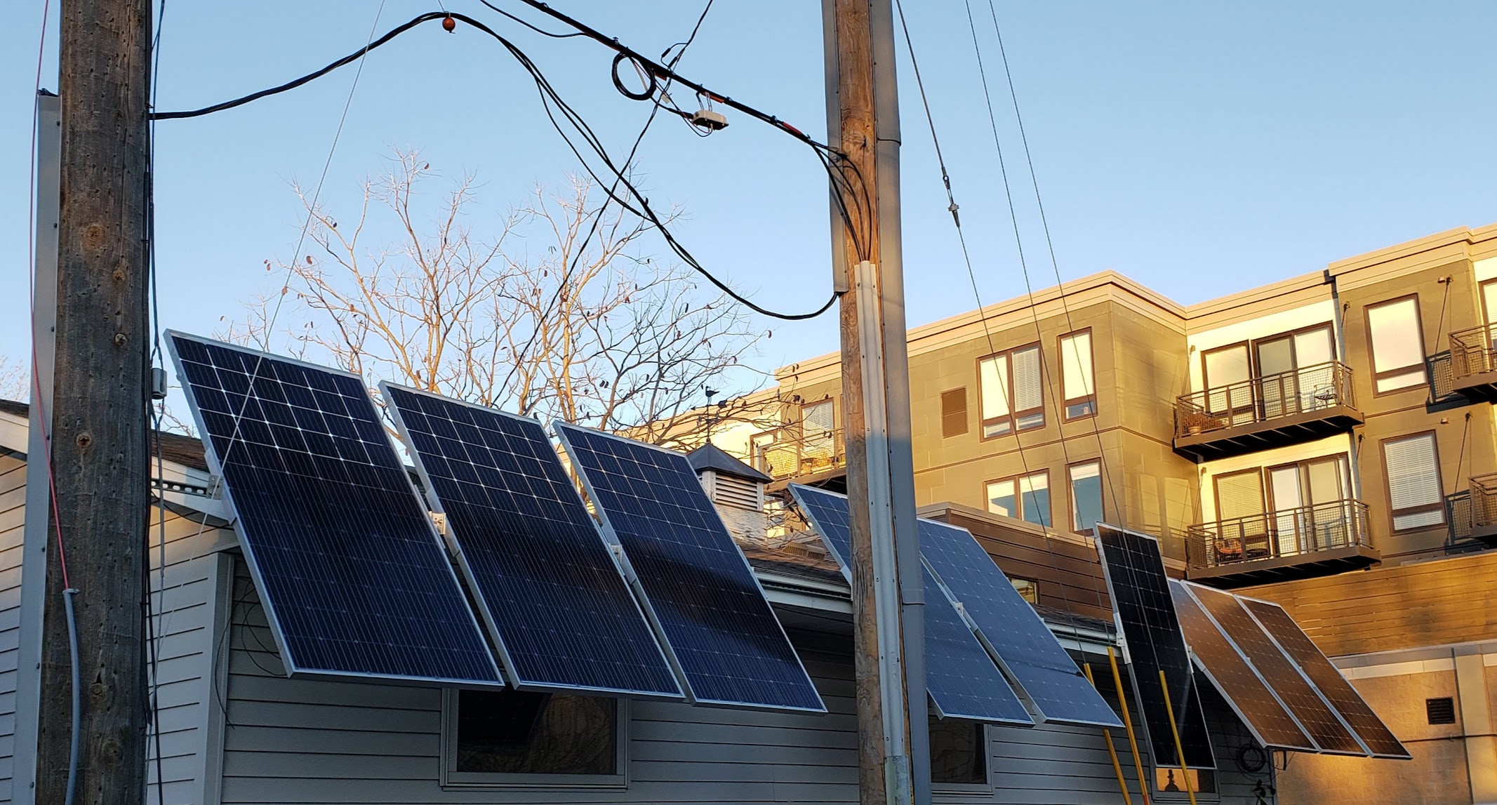
This "potential" 3.33kW array of nine panels is being put up over a several year period (2021-202*), partly due to laziness on my part and partly due to waiting to see if the simplistic mounting system being used would actually work. Waiting for the utility company to remove the now no longer needed pole was also a factor, since its presence is definitely a negative both in terms of insolation and physical obstruction. By the end of 2023 the 9th and final panel was mounted (but not yet hooked up electrically). The 10th panel that was part of the original purchased lot jumped off the roof and did a cartwheel on the pavement below, just to see if the injuries would be fatal (jury still out). The plan is to make the remaining nine panels into a 3S3P array, which would make this a nominal 3.33kW (3,330 watts) array, since the panels are rated for 370 watts individually.
The basic design idea was to mount these panels as safely and simply as possible, while not actually mounting them "on the roof." The plan for this array was always to be "off-grid," with a minimum of fuss and administrative trivia. Since this entire project is motivated largely by a desire to reduce our dependence on foreign oil, the goal is to be able to charge our electric vehicle(s) at home. All local miles driven would use locally produced solar energy. As of 2023, this is already true for our ebikes.
Since electricity is still relatively 'dirt cheap' here in MN (2023), doing all this to save money is not a motivating factor -- although it could be under the right circumstances. Mostly I don't want my effective cost of electricity to go up more than necessary. This means that all solar investment (cash outlay) must be kept to a minimum. This is achieved by buying used solar panels ('new' but already depreciated from full retail cost), using re-cycled parts (wire, mounting hardware, etc.) when available, and doing most - if not all - the installation work myself (see details below).
These ten panels were acquired in the Spring of 2021 from "The Solar Panel Guy" (Carlton, MN, USA). They are 'unused' but where involved in a warehouse fire after manufacture, so were disposed of as 'surplus'. All have been tested and appear to function as if they were brand new.
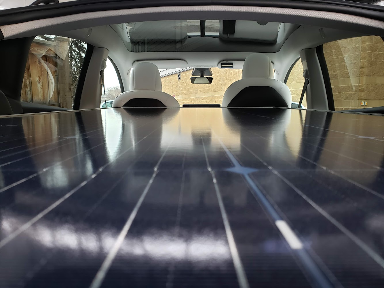
Being able to see the outline of solar cells on the back of the solar panel is the clue that this is a "bifacial" panel.
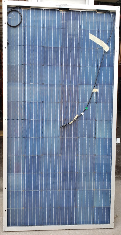
Got the first panel up in November 2022. Note the 'backlighting' effect on the top five rows of the bi-facial panel's cells caused by the snow on the rooftop. This solar radiation (light) caught by the rear of this solar panel can add up to about 30% of its ability to generate electricity. The design of this array is to purposely keep all panels 'off the roof' so as not to interfere with the roof's normal functioning.
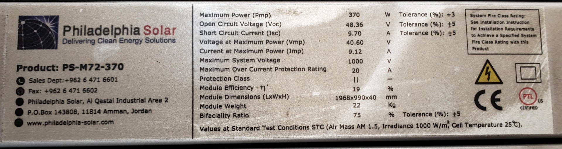
These 'Philadelphia Solar' panels were manufactured in Jordan (the Middle-East country) and are rated at 370 watts each, under ideal test conditions. The max open-circuit voltage of 48 is unusually high due to the large number of cells in this bifacial panel.
How to transport ten commercial size solar panels.
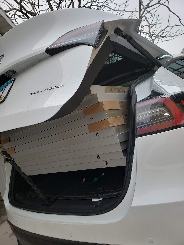
After loading all ten full-size solar panels into the back of a Tesla Model Y, there is still enough space to look around.
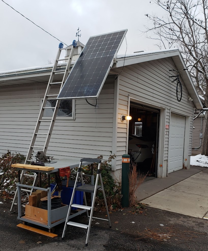
Given the current design of the panel mounting brackets, this tilt angle is at the maximum number of degrees. The plan is to maximize production when the sun is at its lowest position on the horizon (azimuth).
The steep mounting angle of the panels does a great job of keeping the snow off the panels' faces. They were completely clear the day following this snowfall.
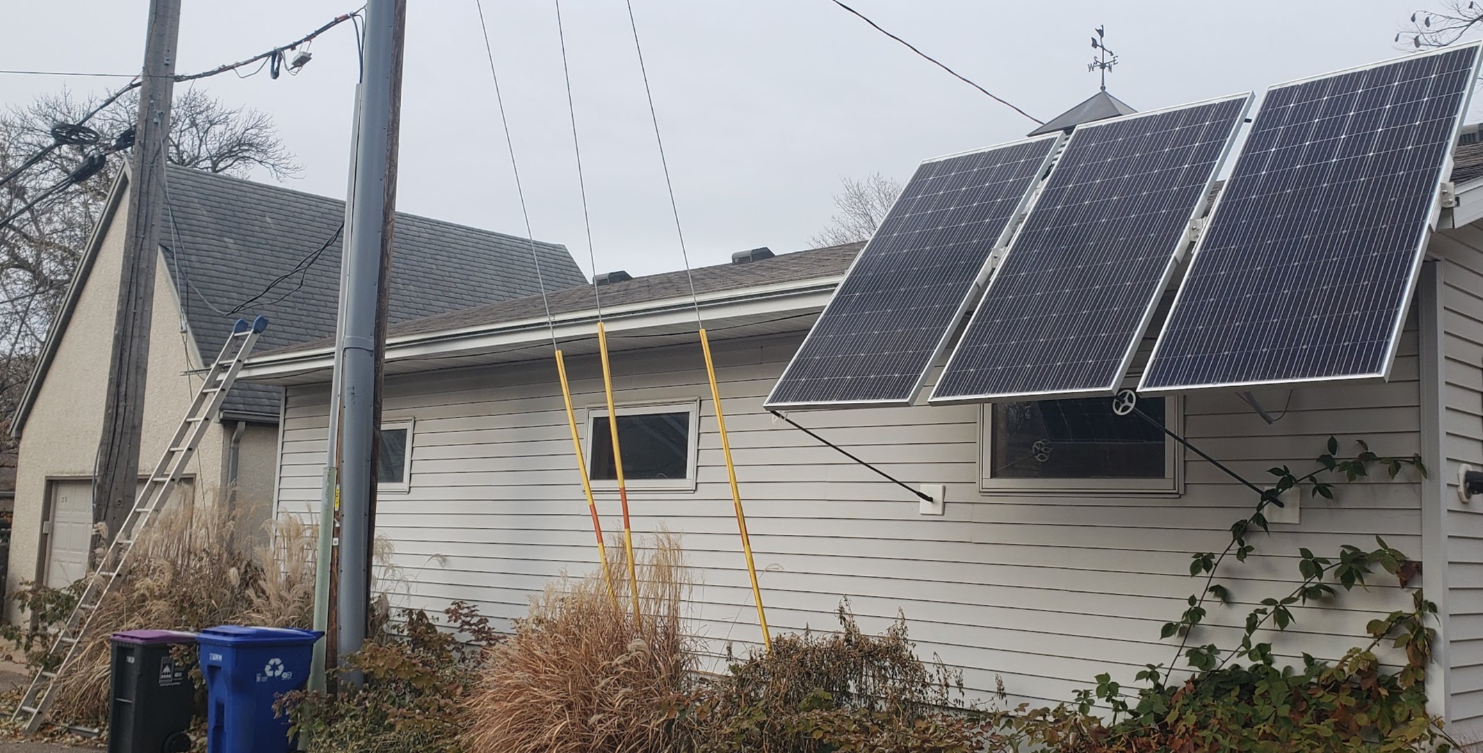
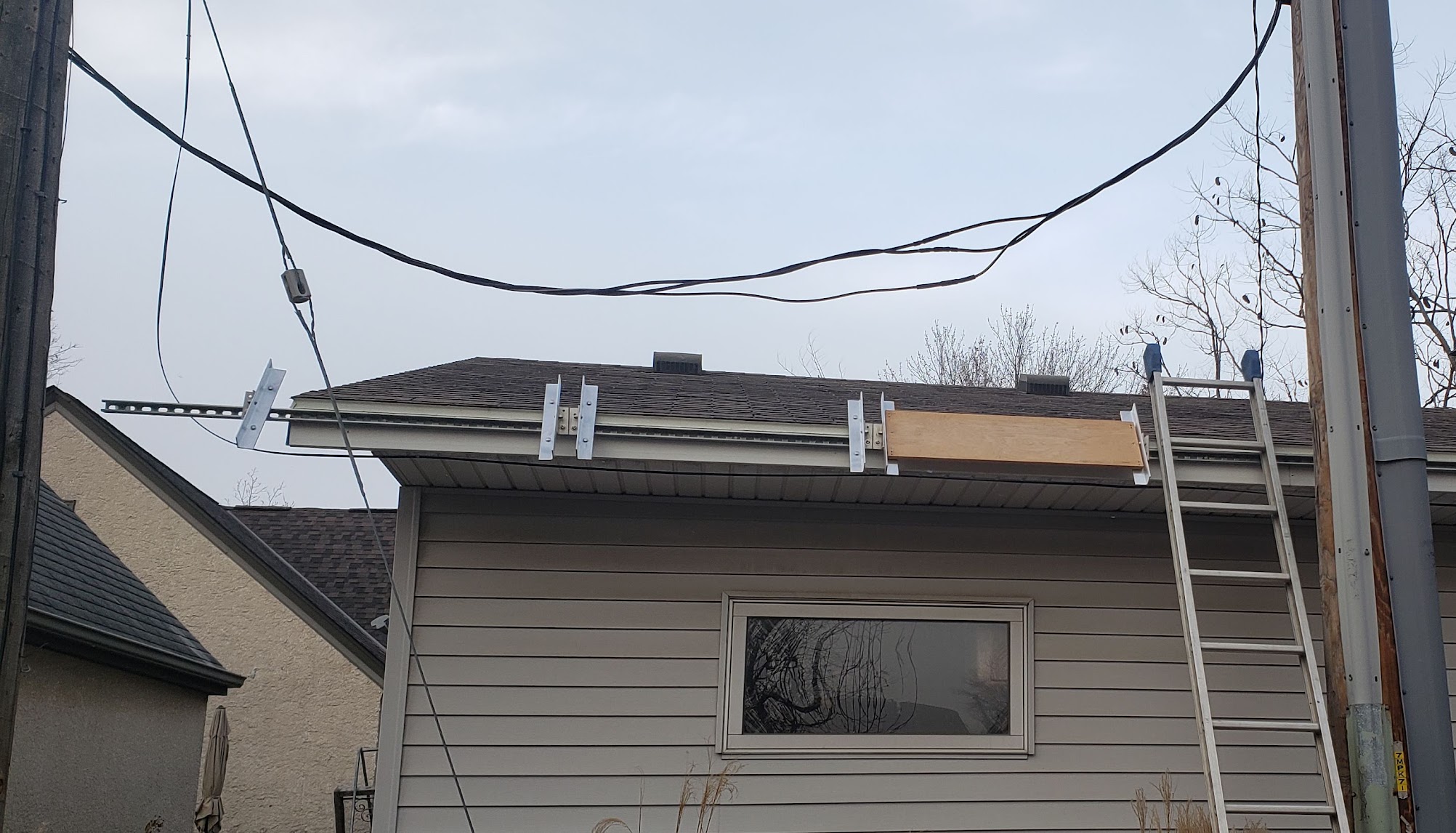
The mounting rail attached to the garage roof joist ends consists of three 10' sections of industry standard "H strut" hardware, often used in industrial electrical installations to support conduits and other equipment. This is made with a relatively heavy gauge of zinc-plated steel and is attached to the garage's rafter ends using stainless steel lag screws. This combination was chosen for ease of installation, strength, corrosion resistance, and cost. Readily available 'captive nuts' can be used with these struts to make attaching anything to them easy to do, and the location of mounting hardware can be easily changed if necessary.
Attached to the main H strut channel are DIY hinge mounts made from 3/16" thick 2x1.5" and 2x2" aluminum "L" bar stock. Each side hinge assembly consists of two sections of the aluminum bar stock and four stainless steel ("SS") bolts: one channel mounting bolt, one hinge pin, and two carriage bolts used as 'keyhole' posts which actually hold the individual panel. Each solar panel needs two of the hinge mounts to be fully supported, and is installed by sliding the panel up over the carriage bolt heads until the panel's keyhole slots drop down over the carriage bolt heads. The solar panels have the ability to 'swing' over a small arc defined by the eaves and the roof itself and can be limited via the friction of the threaded SS bolts used as the hinge pins and (optionally) an external strut between the panel and the wall. An old recycled ski pole or walking stick works well for this, but may ultimately not be necessary if high winds are not a problem.
The following photo shows the 3 panels in late November of 2023. After a full year of service, including some 60 mph wind gusts and a variety of snow loads, the mounting system has not failed in any way. Deeming this to be an approval of the engineering design, preparations begin to mount the next three panels on the westernmost end of the garage (where the ladder is).
Looking at all nine panels now up on the south side of the garage. The camera is facing towards the northwest.
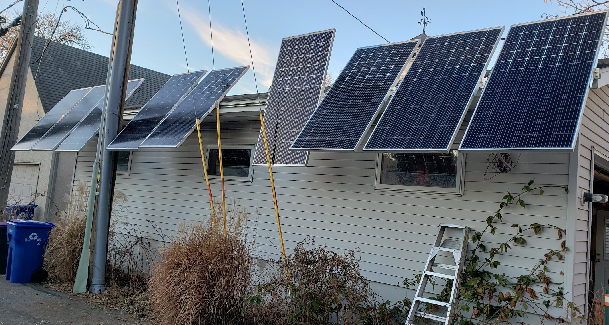
This view is facing towards the east during sunset. It will be interesting to see which of three panel arrays yields the most energy over the course of a year.
Return to Top of Page Return to Main Menu
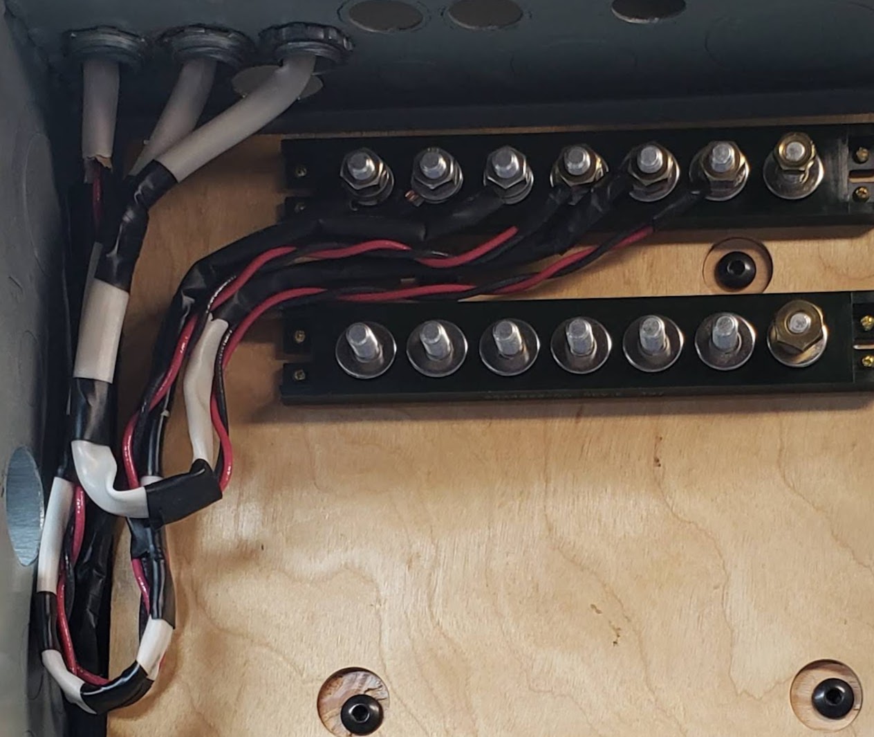
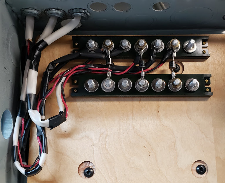
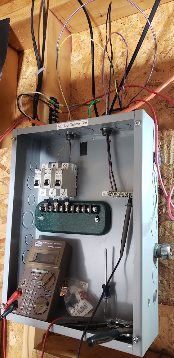
A combiner box (panel) is typically the first device installed downstream from the actual solar panels. The function of this "housekeeping" device is to combine the multiple wires coming from the solar panels themselves into the main PV (photovoltaic) power input to the rest of the system. In our DIY system, it will also contain the devices used to measure the amount of solar energy being produced by the panels, at the array level.
Here we see the original 'prototype' installation of a re-purposed electrical panel on the interior of the garage wall along which the nine solar panels (3x3) are mounted. The wires for the first array are not yet routed into the box, while the second array (yellow wire) and third array (purple wire) are only connected to their respective breakers.
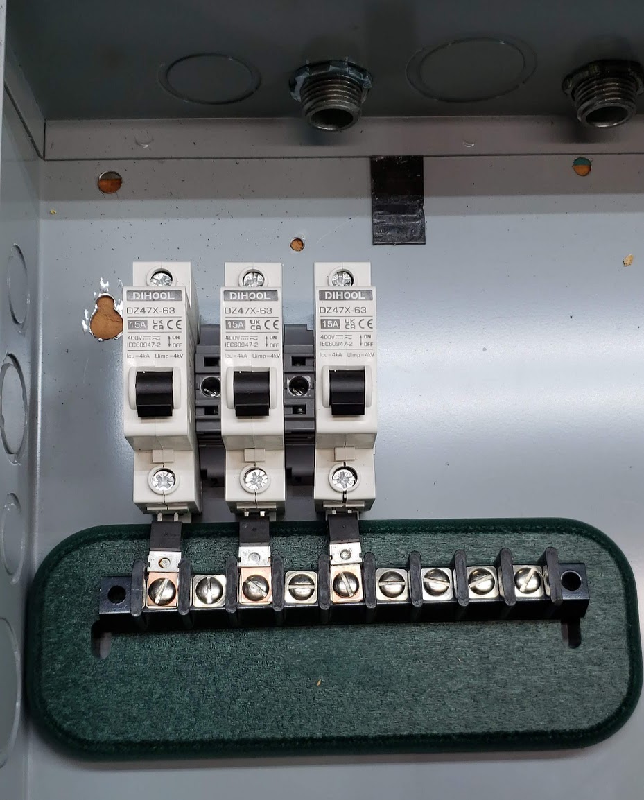
This shows the upper left quadrant of the combiner box with a dedicated circuit breaker for each of the three arrays of 3 panels (9 total panels). Below each breaker is a Schottky diode which prevents any electricity from flowing back into the solar panels, even though these panels likely have their own protective 'barrier' diodes. The measurement units being developed for these three arrays will be placed between the output of the breakers and the inputs of the barrier diodes. Each breaker is 18mm wide, while the gray spacer blocks are 10mm wide. This configuration means that each of the three arrays uses ~ 28mm of horizontal space in the box. (If the measurement units were not wider than this, they could be placed in parallel under each of the breakers.)
Return to Top of Page Return to Main Menu
Solar dump loads typically utilize some fairly massive resistance based heating elements, either to heat air or a liquid. If you need to absorb large amounts of solar energy (thousands of watts), it is usually easier to do it heating a liquid than air. Heating liquids is usually more complex and expensive than heating air.
The idea behind using dump loads is to have something simple, passive, and cheap to utilize the output of your solar panels when your normal system is either not working or you have more energy coming in than your system is designed to use or store.
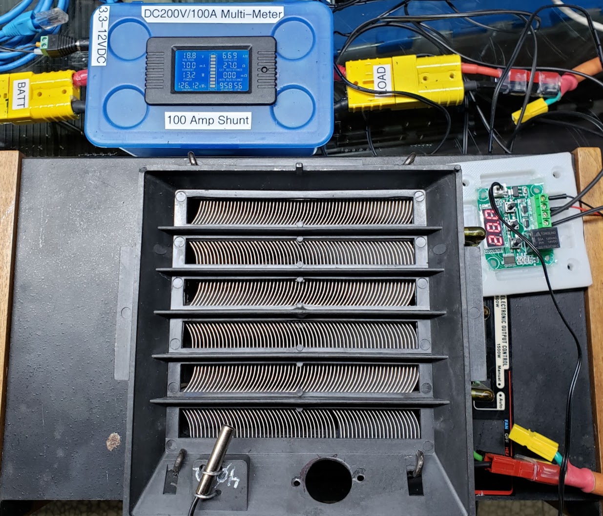
The photo below shows a solar dump load made from a dumpster-dive 1,500 watt electric heater that the owners had discarded because "it no longer worked." Several years' worth of accumulated cat and dog hair had blocked the flow of air through the unit, and the circuit's high-temperature safety switch would shut it off after running a short while. Fortunately for our use the heating elements weren't burned out, and a thorough cleaning resulted in a useable unit. While designed for use with common household 120VAC (single phase) current, the heating elements will work fine with DC voltage up to 140 volts. This is the maximum voltage encountered by my 3S1P solar panel inputs. The key is to limit the current going through the coils, which is accomplished by limiting the number of solar panels connected to this load.
Forced air is used to keep the heating elements within their design tolerances. I decided not to use the unit's original AC fan/motor combination because it could not be made to run with DC (it was not a 'universal' motor). For long term use, the fan will be switched ON/OFF by using a bi-metallic 'thermostat switch' of the right temperature rating. For now, a separate, programmable temperature controlled relay module (W1209) is being used to turn the fan on and off. This makes it easier to work out the correct location and temperature rating of the thermostatic switch that will be used. Note that the energy tracking meter only shows 18.8 volts on the solar panel input because it's near sunset. With full sunshine, this can go to 145 volts and 1,200 watts of power.
Return to Top of Page Return to Main Menu
There is very little that is intuitive about solar power except that it takes sunshine to make it. Lots of sunshine is great, but when it comes to falling on solar panels, there is often less sunshine than we wish. Taking maximum advantage of available sunshine requires being able to measure the amount of energy/power that is being generated by the panels you've installed. Recall that energy describes an actual amount (watt hours) that is captured over time, while power is the *rate* (watts) at which energy is being produced. You want to be able to measure both in order to make the most of your solar system.
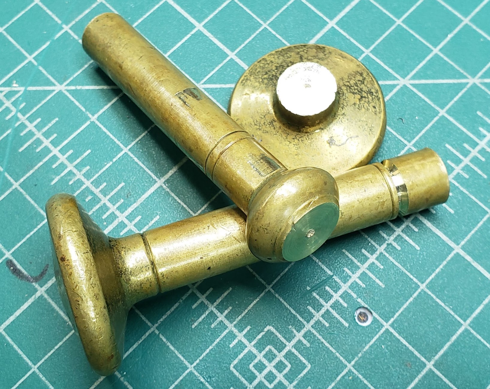
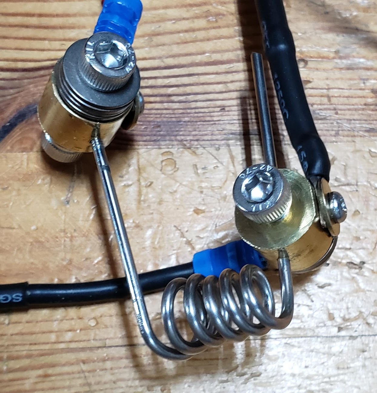
Since simple clamps don't make reliable electrical connections over time, it's time to make some terminal blocks for both ends of the shunt material. This piece of old brass may have been a pestle in a previous lifetime, but will now turn into several shunt terminals.
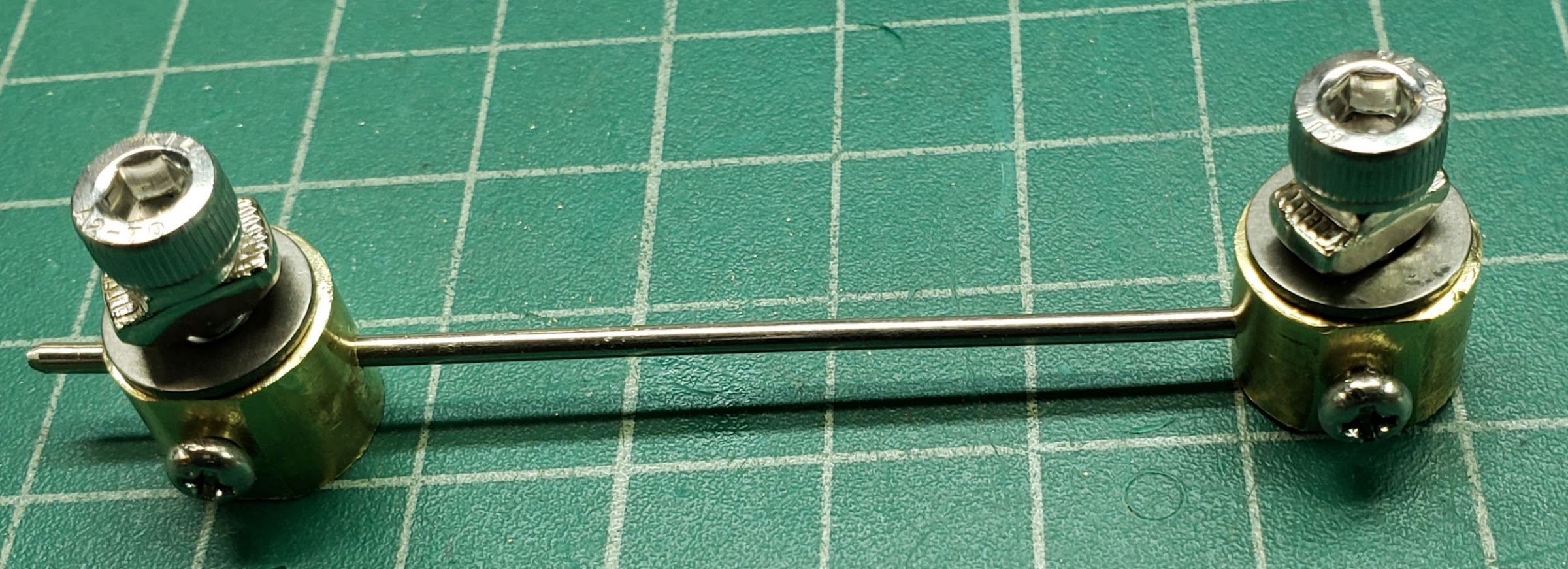
After a bit of machining on the lathe and some drilling/tapping on the drill press, the terminal blocks are ready for testing. The stainless steel (SS) spokes are about 2 mm thick, and the terminal screws are M3-SS for the voltage drop measurements, and M5-SS for the power connections. It may require a third M5 screw as the 'set screw' to fasten the block in a specific place on the spoke and not try to combine the set screw with the power terminal screw.
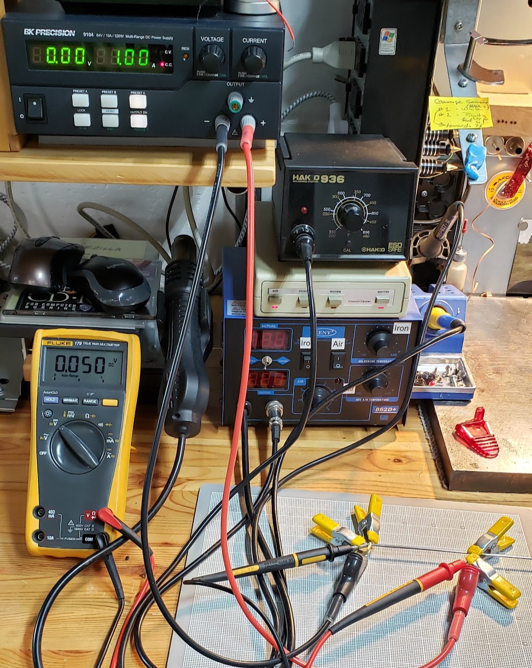
Time to attach the power leads from the bench power supply and the millivolt measurement leads from the digital multimeter (DMM). A shunt that 'drops' 50 millivolts across its high and low ends while conducting exactly one amp of current is a "50 milliohm" shunt. So while the DMM displays a measurement in volts, Ohm's Law gives us the shunt's resistance measurement in milliohms. We do it this way because we don't have an instrument capable of accurately measuring such small amounts of resistance in our shop.
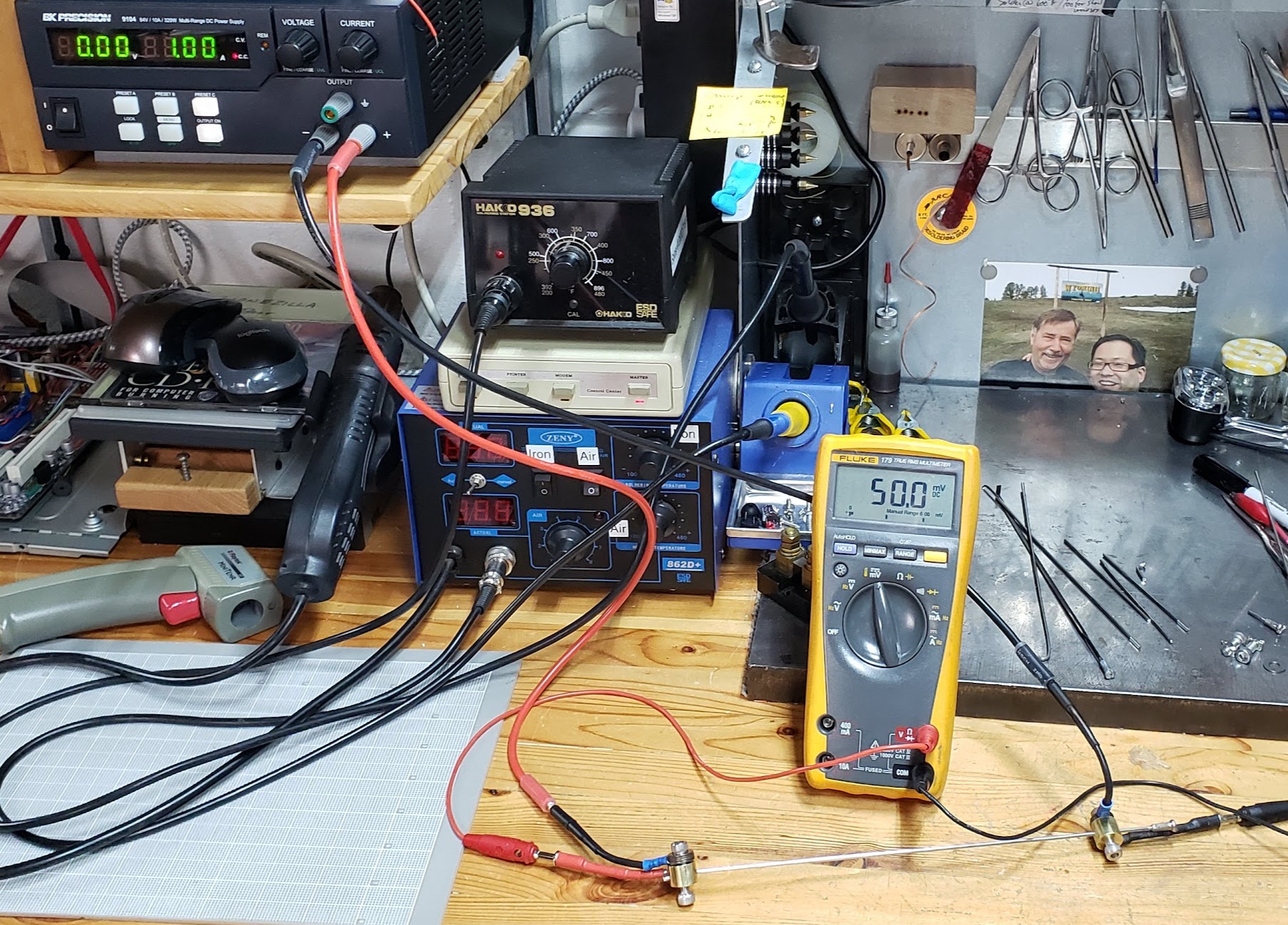
Next up is testing the shunt's ability to perform with higher currents. Each array of three solar panels connected in series (3S1P) will be measured independently, and is theoretically capable of generating 10 amps at 150 volts. The shunt's resistance must remain relatively stable when conducting 10 amps of current, which will heat up when passing that amount of current.
Our bench power supply maxes out at about 5 amps of current, which is being used here. After approximately 5 minutes or so, the spoke shunt's temperature rises to about 85 degrees Fahrenheit and remains there. This temperature is measured in about 68F ambient air, with the shunt terminal blocks acting a bit like heat sinks at the ends of the spoke.
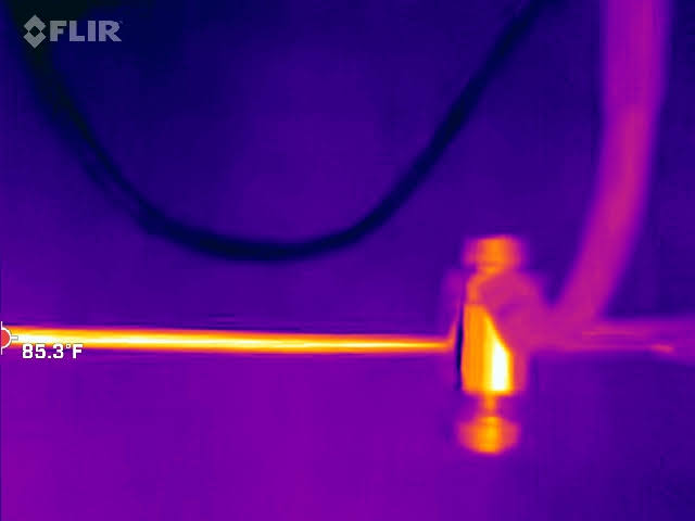
This is using the same re-purposed SS bike spoke but coiled to save space.
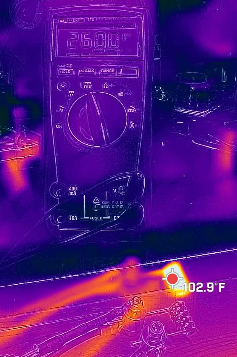
When the infrared camera looks at the coiled version of the shunt with 5 amps of current flowing through it, the voltage drop is 260 milliohms, 10 more milliohms than expected. This increase is most likely a result of the shunt material heating up and increasing its resistivity as a result. However, the 102 degrees Fahrenheit just doesn't seem right since touching the coil with my finger suggested it was *much* hotter. It's possible that the infrared 'signature' of the SS coil just doesn't reveal its real temperature.
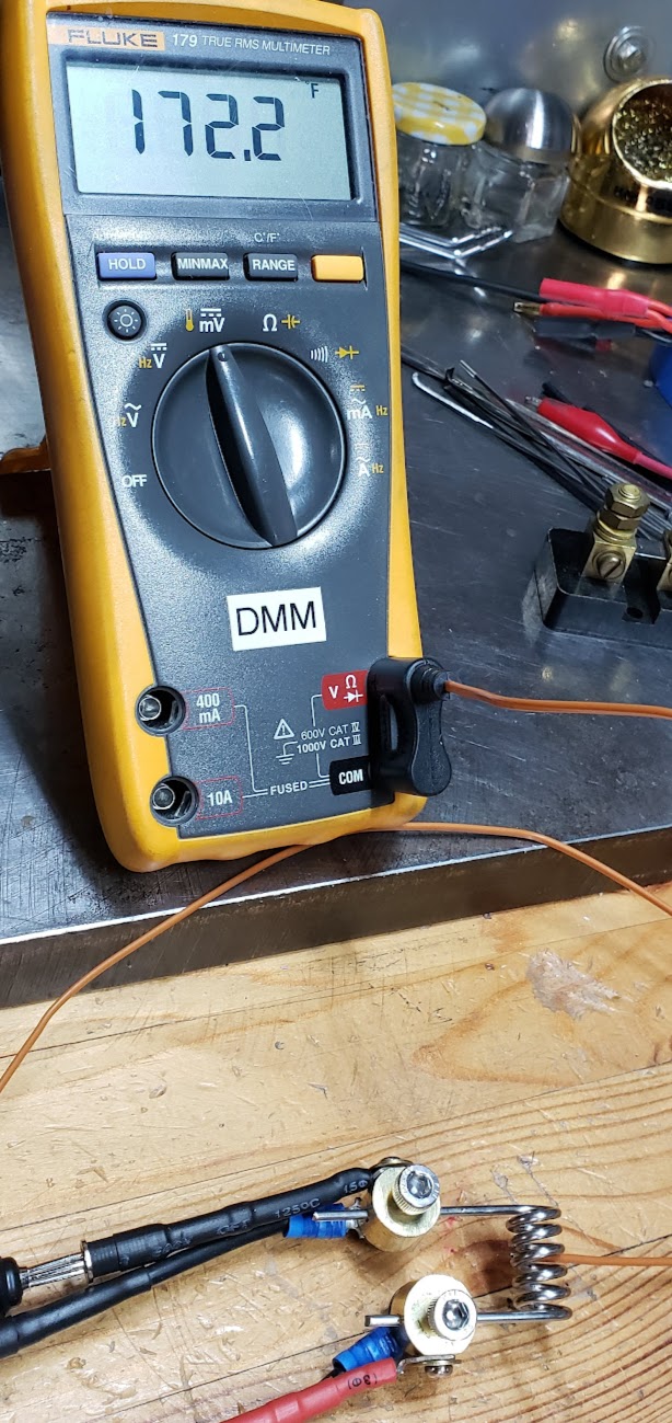
Since an infrared measurement doesn't appear to be reliable in this particular case, let's try a more direct method of measuring the heat of a material. This photo shows the use of a thermistor attachment for the DMM in which the bare wire probe at the end of the brown wire is placed so that it is in contact with the coiled shunt. We expect the hottest part to be near the middle, since it is furthest from the terminal blocks which likely absorb some of the coil's heat.
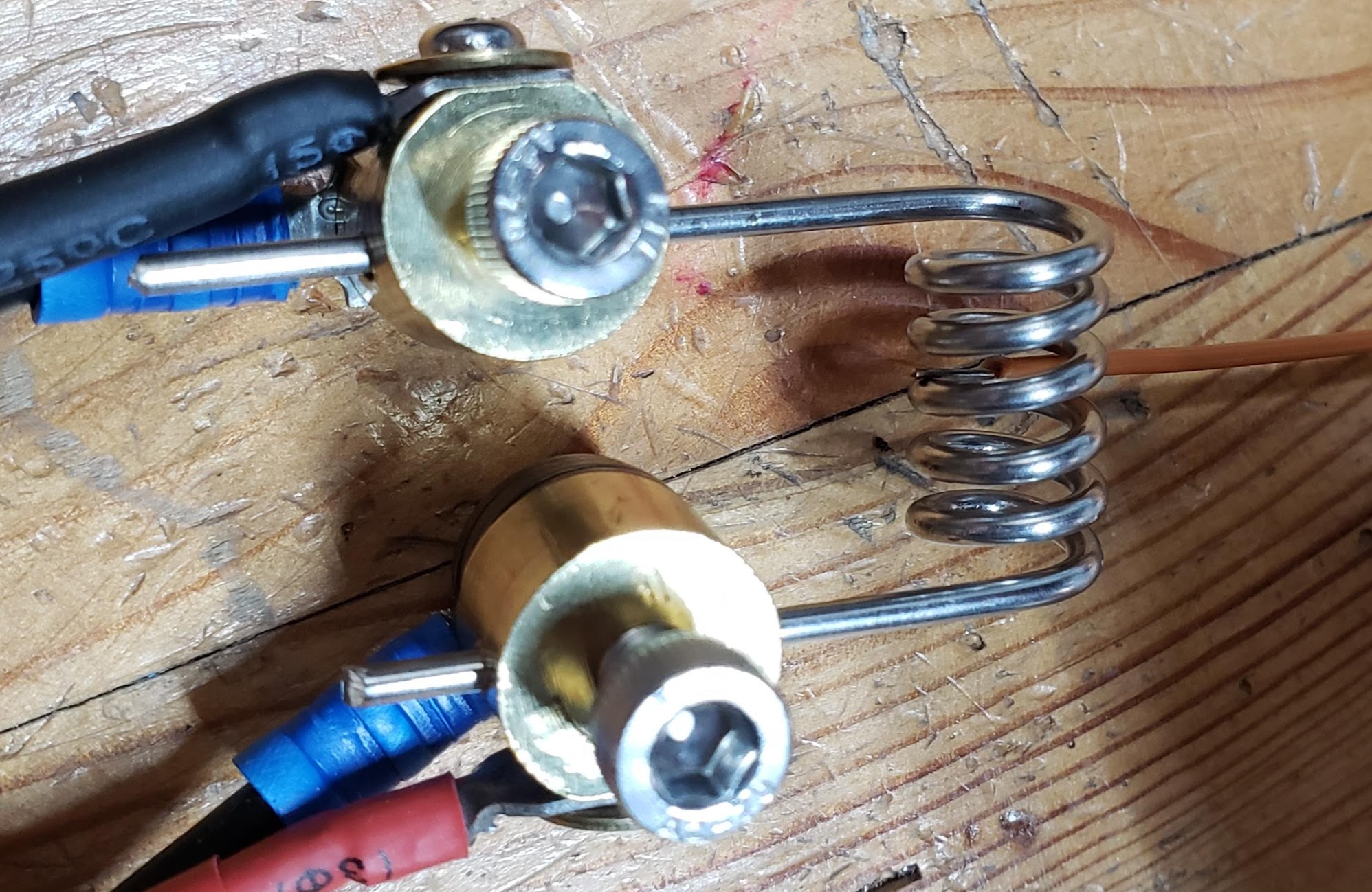
This shows a temperature of 172.2 Fahrenheit, which is much more likely to be the 'real' temperature of the coil. The coil stabilized around this temperature after about five minutes or so of passing 5 amps of current.
Return to Top of Page Return to Main Menu
solar_panels_3_input_panel_showing_diodes /data/photos/biking_pics_and_vids/Justin_with_solar_panel_and_Guillaume.jpg /data/photos/biking_pics_and_vids/battery_bionx_solar_bulk_charge_test_platform.jpg /data/photos/biking_pics_and_vids/streetmachine_solar_cockpit_view.jpg /data/photos/das_overlooking_first_solar_panel_on_porch_root.jpg /data/photos/electronics_supercapacitors_maxwell_3000mf_2-7volts_solar_charging.jpg /data/photos/solar_energysage_dashboard_for_2074_highland_parkway.jpg /data/photos/solar_energysage_register_for_quotes.jpg /data/photos/solar_energysage_register_reason_for.jpg /data/photos/solar_microinverter_IQ7_240VAC_split_phase_2_hot_wires_no_neutral_no_ground.png /data/photos/solar_mounting_for_q-cells_on_porch_roof.jpg /data/photos/solar_panel_q-345-watt_charge_controller.jpg /data/photos/solar_panel_q-345-watt_first_panel_on_porch_roof.jpg /data/photos/solar_panel_q-345-watt_mounting_system.jpg /data/photos/solar_panel_q-345-watt_output_direct_to_paper_shredder_motor.mp4 /data/photos/solar_panel_q-345-watt_specs_label.jpg /data/photos/solar_panel_tent.jpg /data/photos/solar_panels_small_powering_fan.jpg /var/www/html/erowbike/pics/solar_connector_ac_plug.jpg /var/www/html/erowbike/pics/solar_main_circuit_panel_showing_input_and_diodes.jpg /var/www/html/erowbike/pics/solar_panels_3_junction_box_basic_install.jpg /var/www/html/erowbike/pics/solar_panels_3_junction_box_partly_done.jpg /var/www/html/erowbike/pics/solar_panels_3_main_panel_anderson_3x_14awg_single_crimp_pin.jpg /var/www/html/erowbike/pics/solar_panels_3_main_panel_common_grounds.jpg /var/www/html/erowbike/pics/solar_panels_3_on_porch_roof.jpg /var/www/html/erowbike/pics/solar_panels_3_on_porch_roof_2.jpg /var/www/html/erowbike/pics/solar_panels_3_parallel_output_300watt_light_bulb_at_35_volts.jpg /var/www/html/erowbike/pics/solar_panels_3_unterminated_in_basement.jpg /var/www/html/erowbike/pics/solar_power_monitor_by_joshua_griffin.jpg /var/www/html/erowbike/pics/streetmachine_solar_with_front_fairing.jpg