
This is a 24'x36' garage, two separate overhead doors (10'), and one (normal sized) entry door. The cement floor is poured extra-thick, the walls are made using 2x6's instead of 2x4's, and are set on top of 3 courses of 8" cinder blocks to allow a 6'2" person to walk unimpeded under bikes hanging from the rafters. Extra windows all around for more natural lighting.
Typical day in front of the garage...
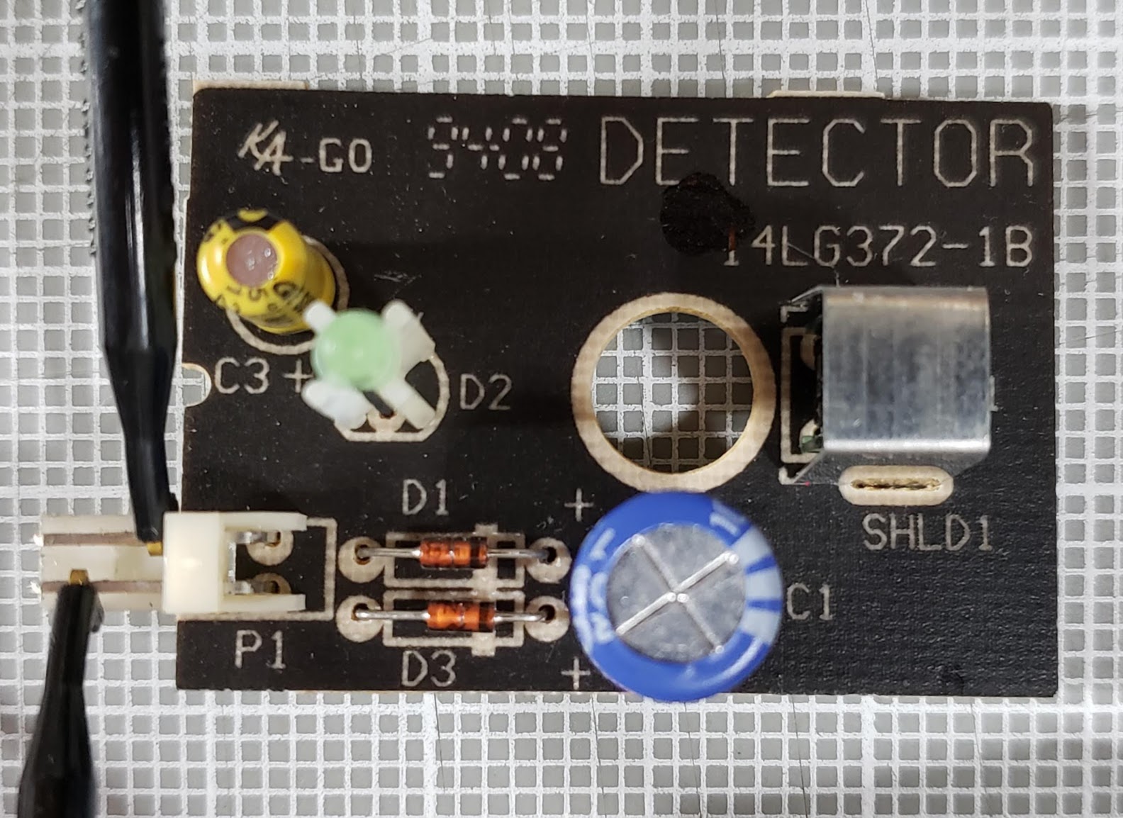
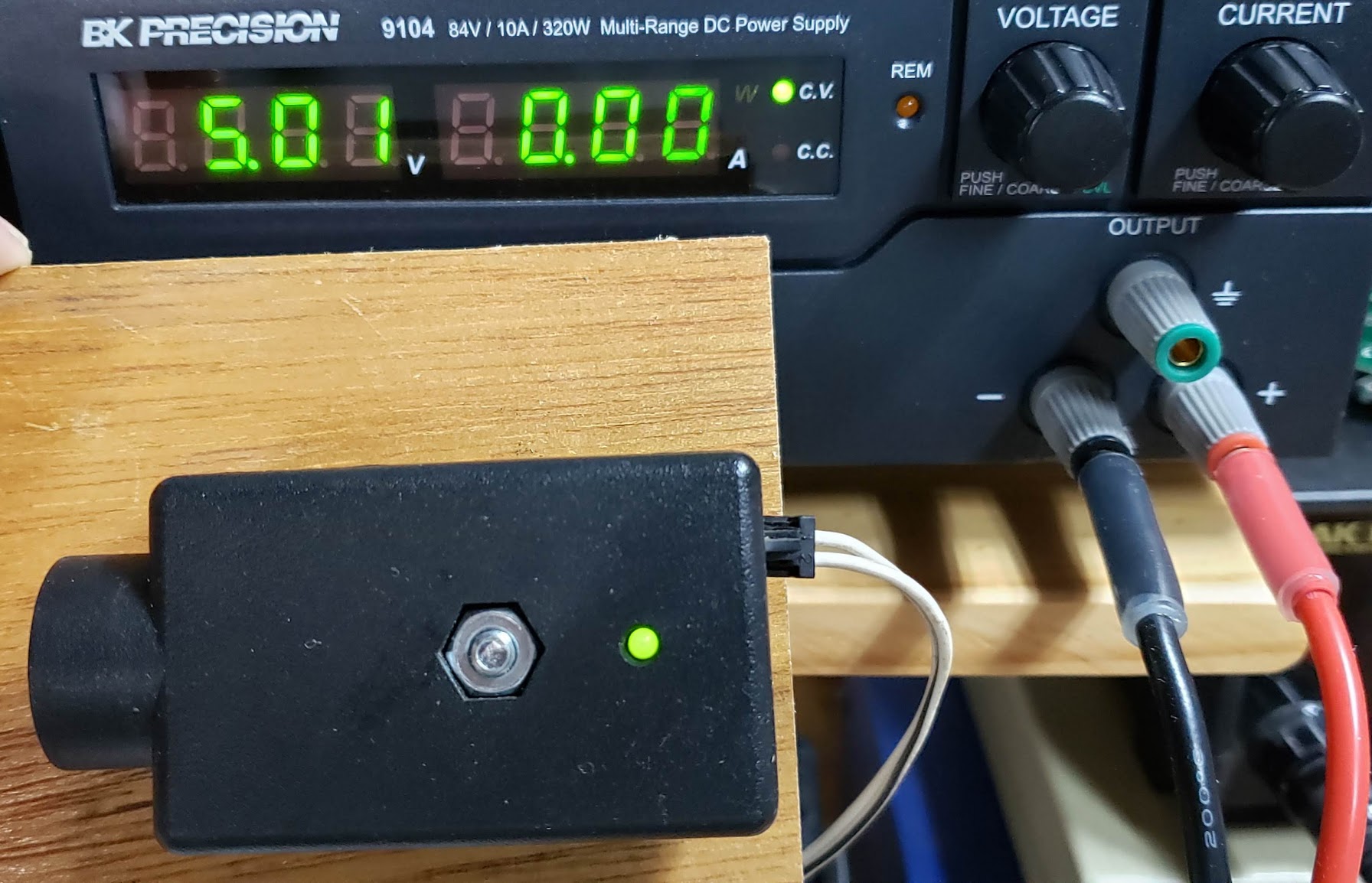
Uses two modules: EMITTER/transmitter & DETECTOR/receiver. Both units are powered by the overhead drive unit, using terminal #2 (white wire/common ground) and terminal #3 (white+black stripe wire/~6VDC). On the test bench, both modules began to function at around 4.5VDC. One of the electrolytic capacitors is only rated for 10V, so it would be best not to exceed that when testing. Each module has one of each wires via a 2 pin male JST-style connector on the module, wired to the drive unit's terminals in parallel (both all-white ground wires to #2 and both B&W striped wires to #3.
Note that this is NOT a simple on/off (binary) switch protection circuit. There is data signal imposed on the IR beam which goes from the emitter to the detector. This is done to keep ambient infrared light (sunshine, etc.) from preventing the circuit's designed functions to occur reliably. It is NOT a LASER beam, and the modules do not need to 'perfectly' aligned for the system to work. Each module has a built-in lens which helps direct and detect the IR light, which is invisible to the human eye. We can tell if both modules are powered up and aligned if both of the green LEDs are lit up, which they should be whenever the door opener system is turned on. Anytime something breaks the IR beam, the DETECTOR module's green indicator LED will turn off. The green LED on the EMITTER module is always lit up whenever power is applied to it.
This is the component side of the detector module. There really aren't many active components on this pcb. The pin on the bottom of the pcb is the board's ground. This was verified by looking at which pcb traces went to the negative sides of the two electrolytic capacitors. The pin on the top (away from the edge of board) is the positive voltage. Remember that applying ~6VDC power to the DETECTOR/receiver will not light up the green indicator LED unless the emitter module is also powered on and shining its IR beam at the detector.
We know this is the EMITTER module because the green LED is lit even though there is no other module emitting IR light. If the DETECTOR were the only module powered up, it's green LED would not light up.
Return to Top of Page Return to Main Menu