| Platform Types | |
|---|---|
| SkyRide - SkyBike | Custom frames with RV motors |
| AL "L" bar stock with RV motors | |
| Skateboard | I-Beam based prototypes |
| Propulsion Sub-Systems | |
| Controllers | |
| Motors | |
| Testing and Usage | |
| Stationary | |
Return to Top of Page Return to Main Menu
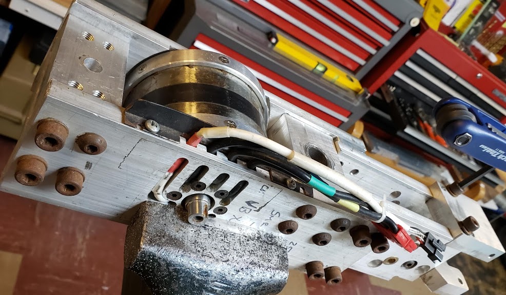
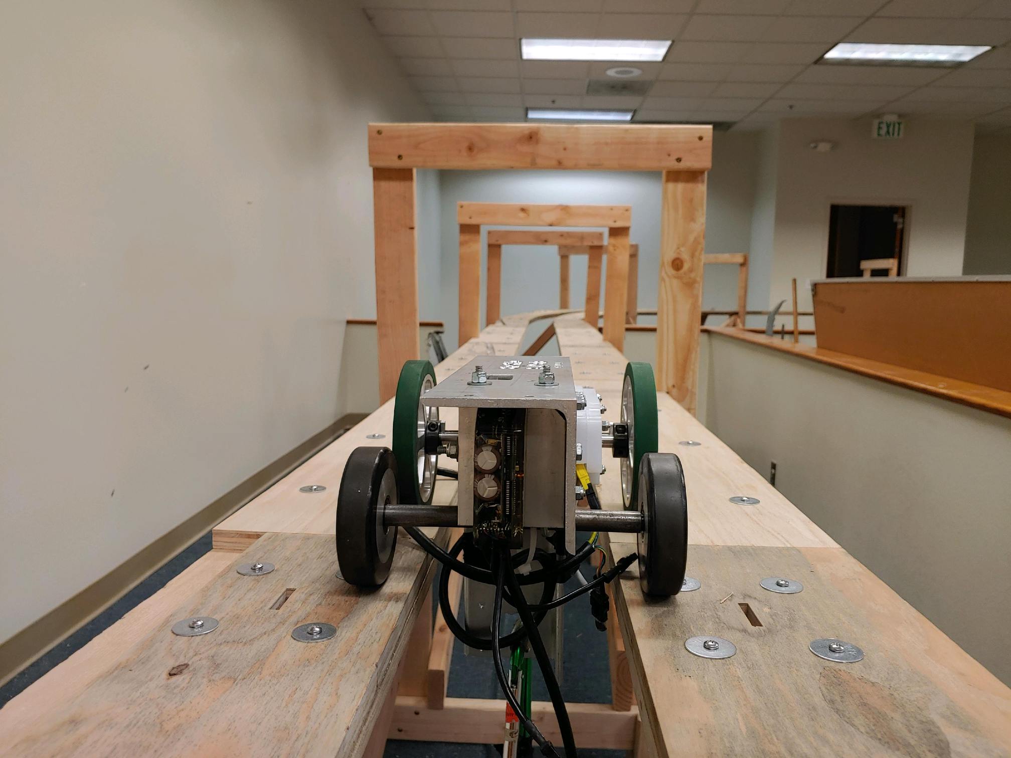
This bogie was frame-based, built out of chunky aluminum parts machined to fit together around an RV-100 dual shaft ended outrunner BLDC, and using a Grinfineon controller mounted on the suspended SkyBike below. The two drive wheels were 'spoked' aluminum wheels with the green rubber treads, while the two passive wheels were 100mm (M8 axles) RollerBlade wheels.
Return to Top of Page Return to Main Menu
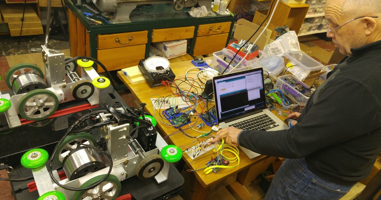
This bogie prototype was based on a simple 4" aluminum bar stock machined to fit an RV-120 dual shaft ended outrunner BLDC. It used the same 'spoked' aluminum wheels with the green rubber treads. The Grinfineon controller was replaced with the Phaserunner, a field-oriented controller ("FOC"), also from Grin. This platform mounted the (smaller) Phaserunner directly on the bogie, simplifying the wiring. The two bogies shown here are actually upside down, with the perpendicular aluminum "L" bar being used to attach the vehicle hanging from the bogie. Bill James of JPods, Inc. is developing the control software. [Feb 2017, Highland Pkwy]
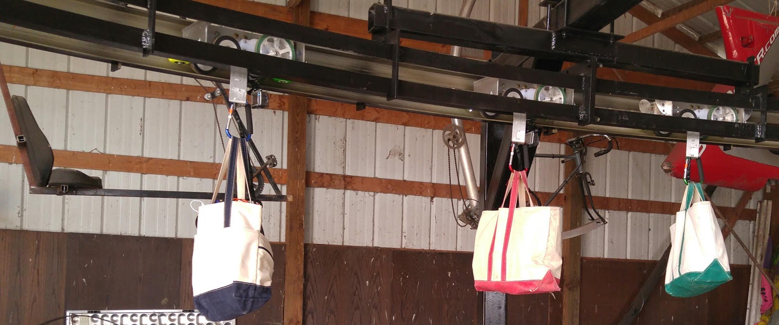
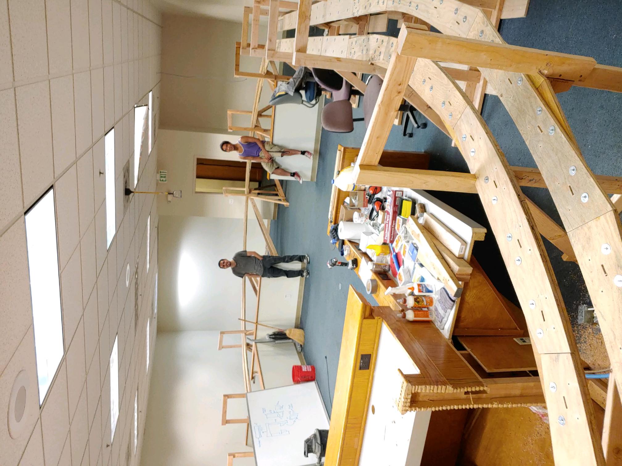
Shown here are the Three Musketeer "L" series bogies on the indoor, circular track in the 'polebarn' in Waconia. The 30' Highland track is built to the same dimensions as this track. The Bean bags (blue, red, green) contain the batteries and act as ballasts. JPod's software is controlling the speed and spacing of the bogies.
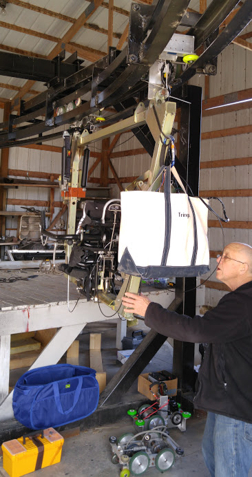
After testing the L-Beam bogies on their own, it's time to strap a closed frame SkyRide->SkyBike frame to one drive and one trailer bogie and continue testing on the polebarn/indoor track. Bill James makes sure all the components are in place. [11 April, 2017]
Return to Top of Page Return to Main Menu
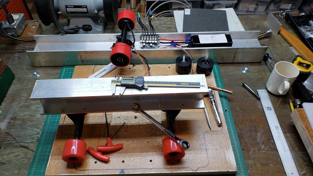
Using standard aluminum I-Beam stock for rapid prototype development was settled on in early 2020. The main factor for determining the ideal I-Beam cross-sectional size is being able to physically place necessary components in practical and safe (protected) places on the bogie itself. Both the controllers and batteries are subject to physical damage, and this would have expensive (controller) and dangerous (batteries) consequences. The I-Beam also has to be long enough to accommate the front and rear "trucks" (axle assemblies), as well as the track-switching assembly. The current length being used is approximately 17.7", since that's a convenient size for being held in our CNC jig.
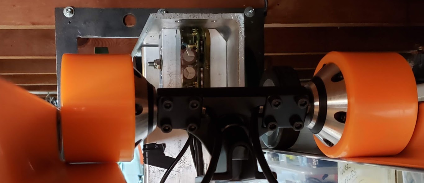
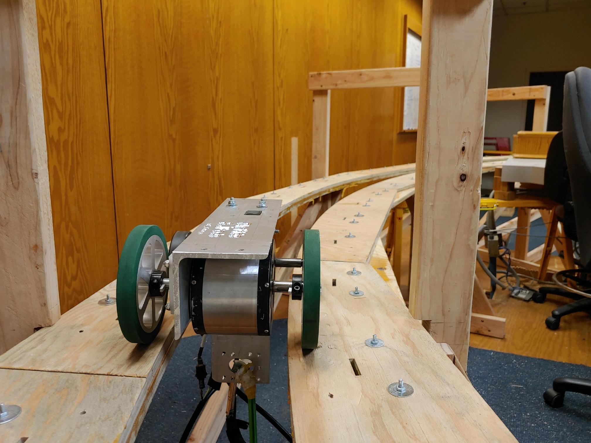
Shown below is a bare prototype with 2.5" I-Beam and 60mm wheels, shown on Highland 30' test track. Will likely try the next size up (3") I-Beam next. The nominal I-Beam measurements used here refer to the top/bottom widths of the I-Beam, not its height (which is greater). Both trucks shown here are passive (non-drive) 60mm wheels, and are spaced (shimmed) out to the end of the axles using copper pipe pieces about 1" long. The trucks we are using on both ends of these bogies are described as "rear trucks" and are designed to accommodate 83mm wheels with built-in hub motors. No axle spacers are needed when these hubmotor wheels are used.
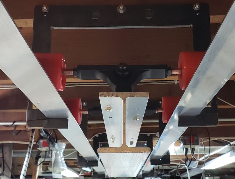
Below you can see both the 2.5" (in the foreground, with trucks attached) and the 3" size (in the back) I-Beam assemblies. The VESC 6.6 dual controller PCB will only fit within the rib cavity on the larger 3" I-Beam. The lipo brick battery will fit "inside" either size I-Beam. Note that all trucks use an elastomer-type bushing as a shock absorber, and as delivered from the factory the axle alignment is not necessarily parallel to the truck's top mounting platform. Using a M14 wrench to loosen the shock absorber assembly while the skateboard is on a level surface, and then re-tightening the assembly will help all 4 wheels being on the surface at the same time.
The configuration of the front and back guide wheels is being tested here, using available 60mm passive wheels. The Highland track has a 190mm gap in the bottom of the track, so the guide wheels will be adjusted for that initially. The San Jose track has a narrower gap of 160 ??? mm. The side-to-side adjustment of the guidewheels appears to work best when they are set to just not touch the edge of the rail when the bogie is perfectly centered on the track. On the Highland track, the wheels run on the inside of "L" shaped aluminum stock which has a radiused 90 degree turn to the vertical, so the hubmotor wheels tend to avoid climbing the radius. This tendency helps the motorized wheels run in the center of the track. Non-motorized wheels have a narrower profile (side-to-side), so they never get that far to the edge of the track in the first place.
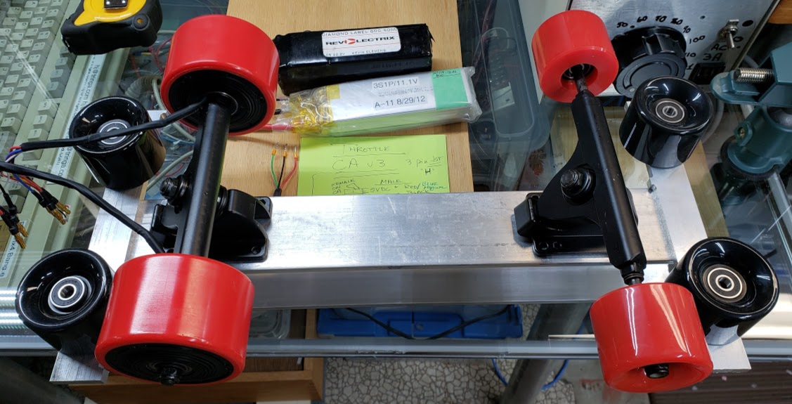
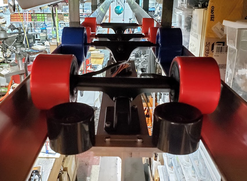
Photo of two bogie prototypes on Highland track. The closer one has the larger 3" I-Beam format and shows the guidewheels mounted. (Note the 14 pound bowling ball hanging from an earlier generation single motor bogie further down the track.)
Five second video showing the bogie being pushed down the Highland track. This version of the bogie is using 83mm wheels in all positions. This is just testing for smooth running and adjusting the guide wheels -- not testing the motors. When the guidewheels are properly adjusted and the track is smooth, the bogie will easily coast 20 feet. This shows that there is relatively little "cogging" associated with these BLDC motors.
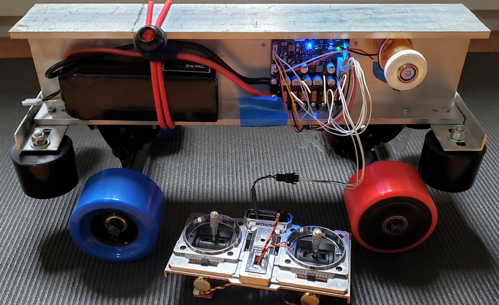
August 1, 2020: Showing the I-Beam bogie powered up, controlled by a center-neutral joystick (5K pot) acting as a two-way throttle. I used the VESC-TOOL app to configure the dual controller's input to be "ADC" (vs "PPM") and set the mode as "Current Center Reverse". The joystick is connected to the 3.3V positive, negative/ground, and the ADC1 pins on the primary Comm (JST-PH-8M) port on the dual controller. Pushing the stick up makes bogie go in one direction, pulling it back makes it go in the other direction. No pressure on the joystick leaves in its center position, which is 'throttle neutral'. Part of the configuration for the controller's "Input" mode includes a calibration process for this particular throttle device. This makes sure that there is no movement when the joystick is at rest, and that there are no "dead zones" in the joystick movements.
Obviously, this hardwired method is NOT a practical way to control the bogie, but this is the first 'live motors' test on the Highland Track. Next up is a little bit of wire management and other cleanup, then this little bogie is ready to go West. Do YOU know the way to San Jose?
This is the I-Beam prototype #1 ready for shipment to San Jose, 6 Aug 2020. The 83mm hubmotors have been electronically matched to the onboard dual VESC controller. The controller's Setup here has been temporarily configured as an analog (ADC1) joystick throttle for testing purposes. The joystick throttle and its JST-PH-8F connector (white wire bundle) will not be included in the shipment, since the bogie will be controlled via a remote (wifi radio) control system on the San Jose Spartan Superway track. The 6S lipo battery (attached via a red bungee cord) shown here, plus a spare, will be shipped (via ground) in a separate box. The SJ Spartan project will obtain an appropriate 'hobby balance charger' locally to maintain these batteries until a more permanent bogie power system is developed.
For a short test run, see short video below the following photo.
Remember that in the video above the bogie is actually running upside down, and a yoga mat isn't the same as an actual track surface.
Return to Top of Page Return to Main Menu
Here a chunk of 1.25"x7"x0.3" scrap aluminum is being made into a guidewheel mounting bracket. We used the HandiBot CNC machine to cut the adjustment slots in the ends of the bar stock. The slots are 1" long and designed to accommodate a stub axle made from 3/8" all-thread, part of which is machined down to 8 mm to fit in the standard skateboard wheels used as the guidewheels. Sideway adjustments are made via tightening the stub axle in the correct location within the slots. Depending on the loads the guidewheels are subject to, it might be adequate to simply use M8 (5/16") bolts as the stub axles for the guidewheels. We'll see if we break anything.
Nothing broke, but it turned out that the thicker aluminum guidewheel bracket had the undesirable side effect of raising the guidewheels higher and leaving less of the wheel to contact the rail. The next iteration of the bogie is using a thinner aluminum, but in an "L" shape, to support the guidewheels. Also, we're using the 5/16" all-thread to fashion the stub axles, and it appears to work just fine (tested with a freely swinging 180 pound weight hanging from the bogie, but on a straight track).
Typically it's a greater effort, in terms of both time and materials, to establish a proper setup of the material to be machined than to do the actual machining itself. Doing many repetitive operations, with extremely repeatable accuracy, helps to make an effective setup jig/holder still advantageous. Shown here is a blank piece of aluminum clamped in the workstand prior to machining the rectangular slots shown above.
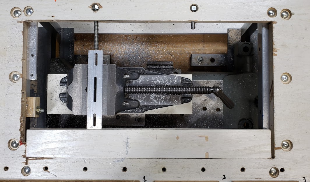
Shown below is a similar piece of aluminum after cutting slightly modified slots, and using a slightly different clamping technique.
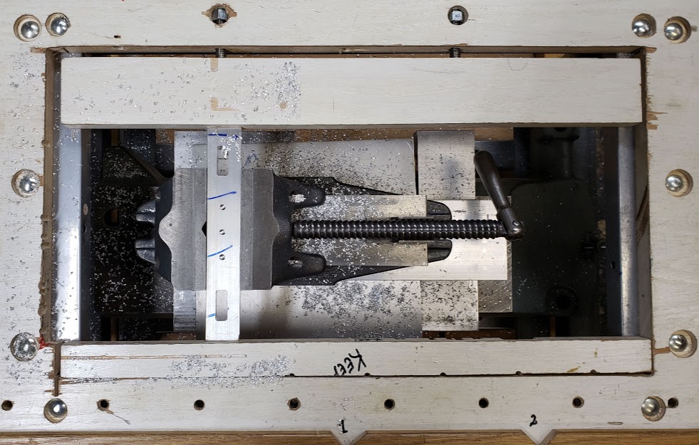
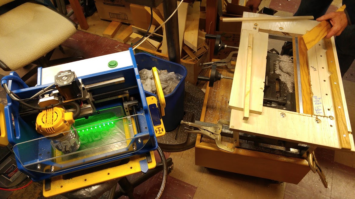
Shown below is a photo of the smaller, 2.5" I-Beam jigged up for machining with the HandiBot. The I-Beam is clamped into the vise below to prevent downward deflection when the cutting bit bites into the material, and is kept from moving horizontally by the two boards clamped against it along its length. Rather than having the CNC's x/y=0 (hardware home position) be in the very bottom left of its machining range, I find it easier to reference all measurements from the physical center of whatever piece is being machined. This gives greater freedom to clamp the piece wherever it will be held securely, and then to simply 'home' the CNC on the center of the workpiece. For all rectangular pieces this is easily done by scribing an "X" to find the center and then marking it. Here I used a countersink on the drill press to make it easier to see the center when the HandiBot is over the workpiece. In this particular instance, there are two 'centers' on the top of the I-Beam, one for each of the trucks and its associated machining operations.
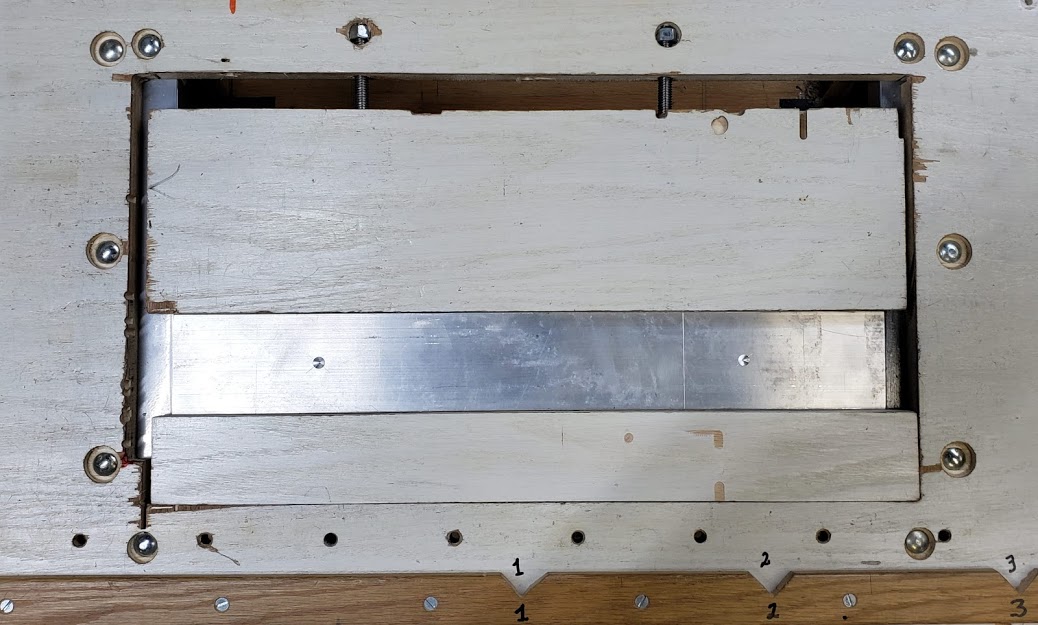
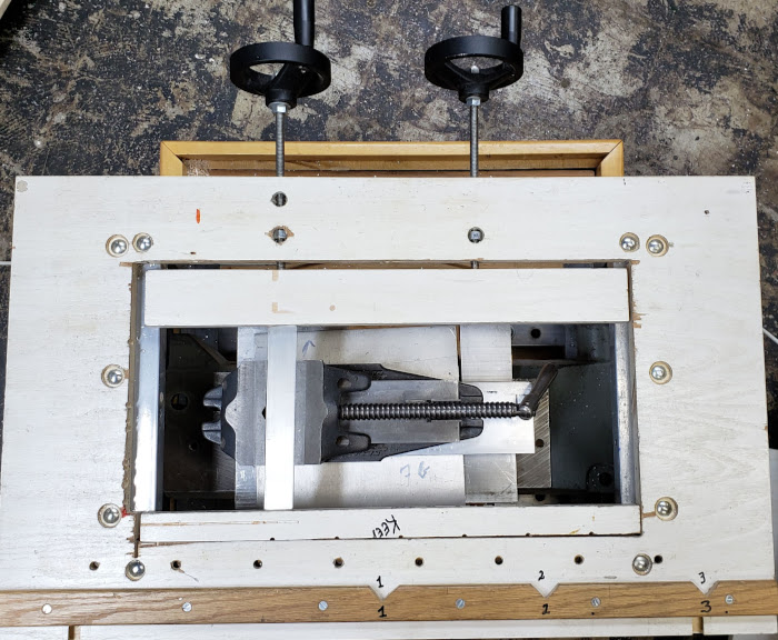
Photo showing the HandiBot portable CNC machine placed next to the workstand while the next piece to be machined is jigged up. While the HandiBot's cutting area is basically 6x8", it can be extended to virtually any size workpiece by using the software's "tiling" feature. This workbench allows for 3 tiles side-by-side, so the effective cutting area for this setup is 18x8", which generally meets our needs.
This shows the three pieces required to effectively use the HandiBot:
1) a computer with a USB port to control the machine (newer versions use WiFi);
2) the HandiBot itself; and,
3) a way to hold the work firmly and conveniently.
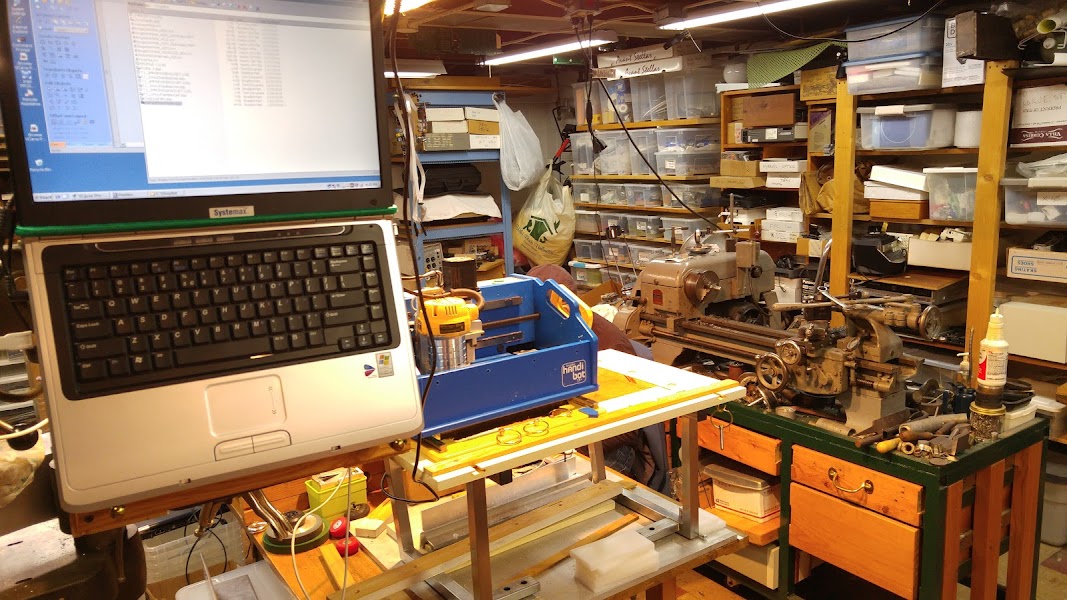
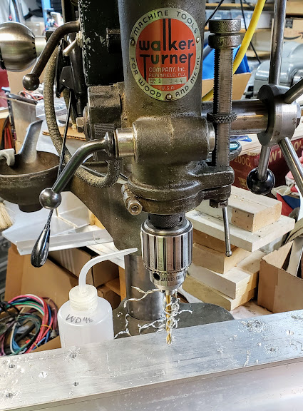
While high-tech machines really expand our capabilities, nothing beats a great drill press when it comes to just shooting a bunch of holes. What I've been doing is using the CNC with a carbide single flute upcut 3/16" bit to machine 'pilot' holes down to 0.1" and then finishing the holes on the drill press with a stock HSS bit, using WD-40 to get cleaner cuts. Since I sharpen my own drillbits and the drill press has a huge motor and a bullet-proof spindle, this saves wear and tear on the expensive CNC bits and machine. In addition to having very accurate pilot holes, you also get a perfect reservoir for the cutting fluid.
Return to Top of Page Return to Main Menu
Short video showing a skateboard-based bogie being pushed down the Highland track. The track is absolutely straight and horizontal, adjusted with a laser level. When the guidewheels are properly adjusted the bogie will easily coast 20 feet. This test track will *not* test any turning or switching behaviors that will be necessary for use in the real world.
Cross-section dimensions of 30 foot Highland bogie test track. The track is built using 4x 15' x 2" aluminum L-Beam bars. The steel plate hanging supports are the same ones used for the SkyRide/SkyBike indoor test track in Waconia. There is a very smooth single track butt joint at the 15 foot (halfway) mark which is barely noticable when even the small skateboard wheels cross it.
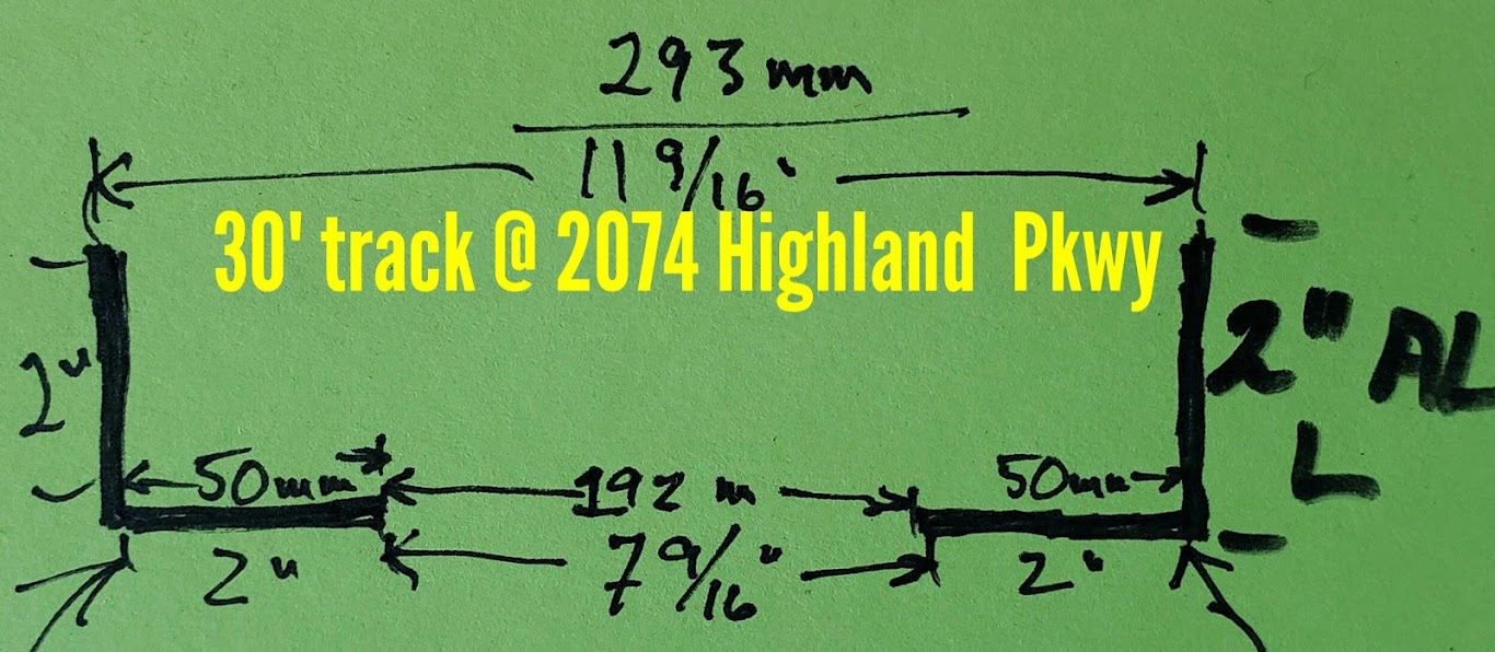
Shown below is the initial test fit of the larger 90mm hubmotors on the 30 foot Highland bogie test track. The maximum outside edge-to-edge distance of the 90mm diameter wheels (same as 83mm wheels) just fits inside the available 293mm space between the track's vertical "L" aluminum channels. However, due to the fact that the "L" channel is the 'architectural' style of bar stock, the inside corner is radiused and presents a shoulder on which the edge of the skateboard wheel rides up on before it contacts the vertical edge of the "L". You can just see some light under the left wheel which points to the possibility of some traction loss under these circumstances. [Note the earlier generation "4 inch L-Beam" bogie in the background on the track.]
Return to Top of Page Return to Main Menu
Several photos of the 10 meter San Jose bogie test track (photos courtesy of Bill James)
Return to Top of Page Return to Main Menu