
| Li-Ion/LiPo Batteries | |
|---|---|
| Overview | A very basic overview of terms and concepts encountered while managing the battery packs on our prototype LEVs. |
| Battery Management System ("BMS") | Connection diagrams, etc. |
| Balancing Cells | Notes on cell balancing. |
| Building Packs | Building and repairing (re-celling) battery packs. |
| Testing Cells | Finding a cell's true energy storage capacity and its general state of health. |
| Resources | Online content to get you up to speed with lithium chemistry cell-based packs. |
| Batteries we use | This describes our current preference for the vehicles "traction battery". |
Our primary purpose for this battery overview is to reduce the amount of confusion that exists when we discuss the virtually unavoidable topic of using stored energy with our LEVs. Unless you park your vehicle at the top of a hill and only ever ride it downhill, you will need to have an onboard device to store electrical energy. While there's no consensus on what to call that device, you will likely encounter the following words to describe it: cell, battery, and pack.
In the following text, and on this site, we'll use "cell" to mean the most basic building block of any energy storage system. It will always be a single, discrete physical container of some sort having a two "poles" - one positive and one negative. The terms "anode" and "cathode" are sometimes used in place of positive and negative, but that distinction isn't critical to understanding and using electrical storage devices. One commonly used container for cells is the "18650" cylindrical format, and it gets its name from the fact that it's 18mm wide and 65.0mm long. If a seller was advertising a "2170" cylindrical cell, you'd correctly guess that it was 21mm wide and 70mm long. If you took apart the battery pack in your new Tesla Model 3 automobile, you could cover your floor with several thousand of these "2170" cells. We don't suggest you do this. Cells can also take the shape of a flat rectangular pouch, making it easier to fit into your smartphone, for instance.
The following photo shows the unfortunate consequences of a drug-inebriated driver of a Tesla Model 3 who ignored our advice. He drove the car at an estimated 100MPH, lost control, and sheared off a telephone pole and two trees before coming to a stop 300 feet later. The force of the several impacts disassembled his battery pack into its component cells, and scattered them over a wide swath of a Corvallis, OR, neighborhood in 2020. It's up to the first responders to clean up the somewhat hazardous mess left behind. The impaired driver, suffering only minor injuries, tried to flee the scene on foot. [photo courtesy of the Corvallis Police Department]

Almost all modern (made within the last 5-10 years) LEVs use traction batteries made up of multiple cells connected either, or both, "in series" and/or "in parallel." Think of old-fashioned flashlights where you unscrewed the rear cap and two "batteries" slid out. These two (or more) batteries were actually "cells", and when inserted into the flashlight end-to-end ("in series"), would provide the voltage needed to make the light shine brightly.
Battery packs will be described by the number of cells "in series" using the capital letter "S", and the number of cells "in parallel" using the capital letter "P". Multiplying the "S" and "P" numbers together gives you the total number of cells in the battery. For instance, a "14S3P" battery pack contains a total of 42 cells, consisting of three 'strings' of 14 cells in series. Each of these strings is then also connected in parallel. In a typical ad for an ebike however, this pack might simply be described as a "52V lithium ion battery."
To gain more "voltage," a battery will use more cells connected in series. To gain more "current" (measured in "amps") and energy (measured in either amp hours or watt hours) a battery will use more cells connected "in parallel." Any cell in any common battery is manufactured using a particular "chemistry."
Those "old-fashioned" cells mentioned above were typically made of carbon-zinc and were rated at 1.5 volts each. They were not rechargeable and would be discarded when the light became too dim. As batteries have improved over time (not nearly as much as we've come to expect), flashlights and other devices now use batteries made up of cells that are rechargeable, but they still are made up of one or more "cells". This is true even if the cells are completely hidden from view, as they frequently are.
The currently (2020's) favored chemistries are in either the lithium-ion ("li-ion") or lithium-polymer ("lipo") families, or other variations such as lithium iron phosphate (LiFePo). It is way beyond the scope of this brief Overview to delve into battery chemistries other than to suggest that picking one over another involves making compromises. Each user needs to decide between such factors as the amount of stored energy a battery has and its ability to deliver a specific amount of power. Other considerations include the cells' life expectancy, weight, safety, and cost.
Power and energy are not the same, and different batteries will be designed to favor one or the other. While this is *wildly* over-simplified, the following illustrates the difference in a basic way. Think of getting a high "power" battery if you want to accelerate quickly and go fast, and a high "energy" battery if you want to go a long distance. If you want to do both, your battery pack will need to be designed with cells capable of doing both.
We'll use the word "battery" to mean any collection of one or more connected cells.
We'll also use battery to describe a single container that appears to be usable to power an LEV. It might have an ON/OFF switch, a locking device - often with a key, a gage of some kind to indicate whether it's full or empty, a port for recharging, and certainly a connector or cables which supply electrical power to the vehicle. We rely on the seller's description as to what is actually inside the container. Many low-voltage batteries contain only a single cell, which contributes greatly to the confusion.
We'll use the word "pack" to mean any collection of connected batteries.
We'll also use pack to describe a rather BIG container used to store electricity where we have no idea of what's inside that container. As far as the average user is concerned, the terms packs and batteries could be used interchangeably.
The word "traction", if used to describe either a battery or pack, simply means that it's used to primarily power the motor(s), as opposed to lights and other accessories on the LEV. A traction battery may, of course, also be used to power the vehicle's accessories, and frequently is. When using accessories powered by the traction battery, provisions need to be made to match the operating voltage of the accessories to the operating voltage of the traction battery. Search the internet for "buck converters" if the voltage needs to be reduced (common), and "boost converters" if it needs to be increased (uncommon).
Batteries don't last forever (not yet). How do you know a battery has reached its end-of-life ("EOL")? The best answer is "when the battery no longer does its intended job". If a car battery no longer starts the car, or a flashlight battery no longer shines brightly, or your bike battery no longer has the range of miles that gets you where you want to go. Another reason to stop using a battery is when it's no longer safe to do so.
Additional clues pointing to batteries having reached their EOL:
If any of the above still leaves you wanting to know more, simply 'google' the relevant terms and start following links.
Return to Top of Page Return to Main Menu
Almost all batteries designed for ebikes and other light electrical vehicles (skateboards, etc.) will include a BMS. For that matter, even small appliances using lipo battery packs, such as laptops and lawnmowers, will also have batteries with an internal BMS. Typically they will be mounted inside the battery case and invisible to the user. They are meant to be an integral part of the battery pack and if they -- or any of the battery cells -- fail, the entire pack is considered to have failed. If the user is conscientious, the pack will be recycled responsibly.
Speculation abounds as to how many "perfectly good" battery cells end up in the world's landfills each day. A few minutes on youtube reveals a large community of hackers who take apart these failed battery packs and extract usable cells for a second life of storing electrons.
Another common definition for "BMS" is "battery murdering system." This definition is based on the common occurence of a BMS itself failing, while all the individual cells in the battery are still perfectly fine. Either eventually or immediately, depending on the battery's design and the nature of the BMS failure, the battery's cells will also fail and the entire pack becomes useless. The device using the battery will report this failed condition and the user is forced to replace the battery pack. Frequently, the expense of a replacement battery causes the user to either buy a new device containing a new battery, or discard the entire device (in disgust).
Watch this 18 minute youtube video by Shawn McCarty, recorded on June 17, 2016, for a well-reasoned argument in favor of NOT using a BMS in your lipo battery pack, as well as how to do this in a safe and effective manner. Unfortunately, Mr. McCarty's method, while sound in practice, requires more effort than many users will want to invest in their use of larger battery packs. His method involves electrically splitting larger packs in half and using balancing ("hobby") chargers to charge/balance them when necessary. Battery packs using high quality lipo cells and balanced when they left the factory have a tendency to remain *reasonably* well balanced over time. This property can be taken advantage of by doing most recharging using a "bulk" charger, which means simply applying the desired voltage and current to the pack's discharge leads. Periodically the user recharges the pack using the balance charger mentioned above to bring all of the cells back into balance.
To split the battery electrically requires opening up the battery pack itself, which frequently be quite a challenge. Then you must figure out where the two places are that the electrical connections must be interrupted to split the pack. Assuming that we're splitting a 14S/52V battery pack, we need to figure out where to break the positive and negative rails to essentially make two 7S/26V batteries. We also need to convert the single 14S balance plug into two 7S balance plugs to use with the balance charger. (See * elsewhere on this page for details on how this is done.)
Assuming, for whatever reason, you decide to use battery packs with a BMS, or need to repair/replace a BMS, or otherwise use a BMS, here is what you need to know.
The BMS is typically a printed circuit board (PCB) containing surface mounted electronic components, at least one connector socket for a removable plug with the cell balance leads (wires), and several heavy-duty solder pads to make the relatively permanent connections to the battery cells and to the pack's recharge port. Some BMS boards will also support optional features such as an ON/OFF power switch, LED voltage meters, and a USB port to allow cell phone charging while you ride your bike.
Probably the most serious shortcoming of the *typical* BMS, found in the majority of consumer devices, is that they aren't really a battery "management system" at all. A reasonable expectation for a BMS would be that it automatically and continuously kept all cells in the pack in perfect balance (to whithin several millivolts). This expectation is only met by an "active" BMS, which most aren't. The typical "passive" BMS found in ebike battery packs is designed to prevent massive overcharging, and to prevent using the battery when any of the cells are depleted to some minimal voltage level. The overcharging prevention is usually accomplished by "bleeding down" cells which happen to arrive at the maximum of 4.2 volts before others in the pack. The undervoltage protection is usually accomplished by the battery just being 'turned off' during your ride. The fact that an active BMS is much more expensive than a passive one likely explains why your battery pack doesn't contain one.
The following section shows some well-prepared information found on the web in the middle of 2020. (text and diagram courtesy of https://diy-eboard.com/bms/)
==========================================================
Understanding the wiring
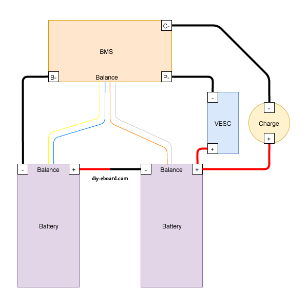
Please look at the diagram your BMS comes with, either in the box or from the place you bought it from. Not all BMS's are the same. Most BMS's have three 'solder spots' which should be labeled CH- (or C-), B- and P-, and a balance cable connector. Some BMS's may differ (from) this.
The BMS won't connect to any positive wires.
Let's start with the solder spots.
Each of the three solder spots needs to be wired into different parts of the circuit, that's why they're labeled differently.
Typical connections to BMS, batteries, and controllers.
==========================================================
We have several batteries that have failed BMS boards, or have had the BMS boards removed because they were proprietary and other components in the system failed (like the BionX 13S/48V pack). The cells in these batteries are still good, and the packs tend to stay balanced even when simply bulk charged and used normally (with controllers capable of protecting the batteries by having an appropriate LVC capability). Our plan is to continue to use them this way and to occasionally balance them, as necessary. To make it possible to balance/charge them as a single process, the BMS can be a generic one not mounted inside the battery pack. In the diagram above, the controller ("VESC" or any other controller) is not involved, so the BMS main negative power output (large) wire going to the controller can be left disconnected. The "P-" (power negative) solder pad on the BMS can be ignored.
The charger power supply will connect its positive (red) wire directly to the positive output of the battery pack, and the negative to the "C-" (charger negative) solder pad on the BMS. since we like to charge at around 1 amp (50 watts for 50 volt batteries), the charger cables can be relatively small gage wires. We'll probably use 12AWG silicone wire anyway to allow for LEV handling challenges. Since we have standardized on 15-45 amp Anderson PowerPole (APP) connectors for our higher capacity power supplies, we'll also use the APP connectors for our charger ports, as appropriate. We already have APP-XLR adapters as well, in case we want to use chargers with XLR plugs. All battery packs we want to charge this way will need to have balance leads attached to their internal cell series and brought out to an externally accessible balance plug. The Luna Mighty Mini 14S pack, whose BMS failed, is a good example of this, having the 14S JST-PH female plug hot-glued to the outside of the case. The following photo shows what a bit of exposure to rain can do to corrode the BMS and causing it to fail. This particular battery, even used without the BMS and bulk charged (no balancing) for several years, has all of its cells remain balanced to within a few millivolts. There is no substitute for packs made with high quality *matched* cells at the time of manufacture.
When charging an LEV battery made up of higher voltage strings (e.g., 36-48-52 volts), it is much more difficult to do "balance charging" of the pack without a built-in BMS, but it can be done. The approach we favor is to electrically 'split' the pack so that it can be charged with an available 'hobby charger' which is inherently capable of doing balanced charging. The challenge is that currently (2021) available hobby chargers are limited to charging up to a maximum of about 30 volts, or 8 cells in series (S8). An example solution would be to take a 14S (52V) pack and split it electrically into two 7S packs, and use a hobby charger to balance charge both 7S sections at the same time. We use a Revolectrix CellPro PowerLab 8 to accomplish this.
Return to Top of Page Return to Main Menu
Balance leads (wires) are typically 20 to 22AWG and use JST-XH (2.54mm-0.1") or JST-PH (2.0mm) connectors. Be careful about encountering JST-EH connectors, whose 2.5mm pitch is very close to the JST-XH 2.54mm spacing. Balance connectors will have one more wire than the number of cells, so a 13S battery will use 14 conductor balance wire harness. Traditionally, 13S/48V batteries and lower have used JST-XH connectors, while the 14S/52V batteries and higher have used the JST-PH connectors, presumably to keep the connectors from getting too wide (the JST-PH family has a 'finer' pitch than JST-XH).
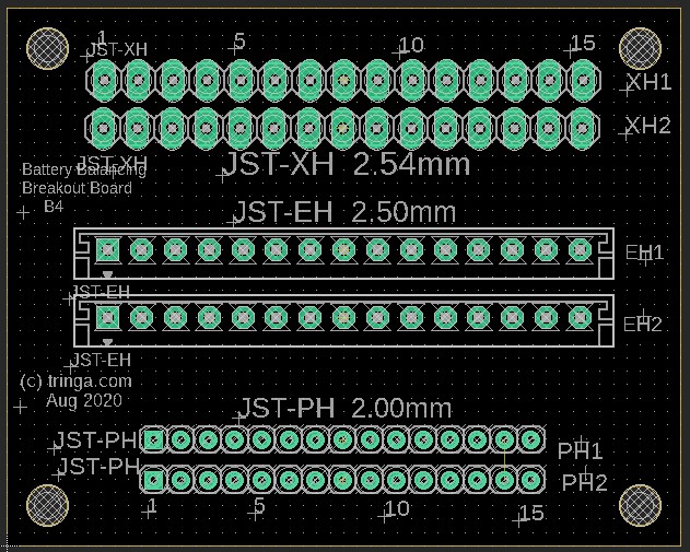
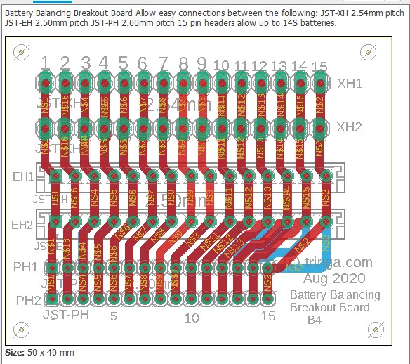
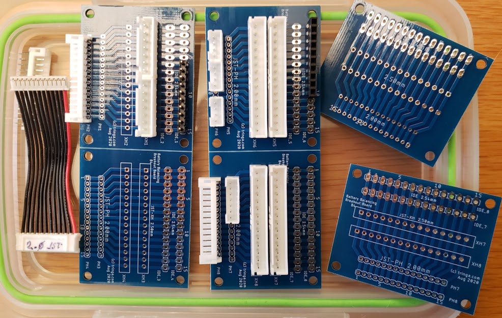
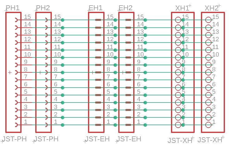
The following shows an attempt at making a tool to deal with the three commonly encountered connector pitches in the current LEV lipo battery pack world. Soldering connectors and loose wires to a printed circuit board (PCB)is much easier and more reliable than trying to solder wires directly to a 2.00mm pitch connector, especially if you're over 70 years old (which some bikers are). This "breakout" PCB simply connects the 15 pins on one connector to all of the corresponding pins on all of the other connectors. There is no requirement to populate any of the connectors, or to utilize any of the pins, other than those needed for a specific task. Breakout boards are becoming increasingly common tools as electronic devices are made ever smaller, and manual access to their connections becomes more challenging.
For the cost of about $5 for the actual manufacturing, plus $20 for shipping, the chinese company Seeed Studios will accept your design files and send you 10 high-quality finished PCBs. In this example, because these breakout boards are small (40mm by 50mm), we'll "panelize" them and fit four individual boards on each PCB (80mm by 100mm), so we'll end up with a total of 40 breakout boards. Given the total cost of materials and shipping at about $25, this results in a cost of about 63 cents per breakout board. The software being used here is by Eagle, version 9.5.1., which is not the most recent version at the time of this writing (Aug 2020).
The widths of the traces have been made as wide as practical and have been routed on both the top and bottom of this two-sided board to allow as much current as possible. Since we rarely charge packs at more than 150 watts or balance them quickly, none of the traces are ever likely to see as much as 2 amps, which these will easily handle.

Return to Top of Page Return to Main Menu
Photo of several JPods' Maxwell "BOOSTCAP" super-capacitors (ultra-capacitors) on the workbench. These are rated for 3,000 Farads (NOT "microFarads"!!) at 2.7VDC. To use them at 12 volts, a minimum of five need to be connected in series to achieve a maximum working voltage of 13.5. Since this leaves no safety margin for over-volting the caps during charging, we're planning on using six in series (6S) instead, for a maximum working voltage of 16.2 VDC. The Malectrics spot welder we're using prefers a maximum input of 14 volts, so we'll limit our supercap pack charge level to about 13.5VDC, which should keep everyone happy.
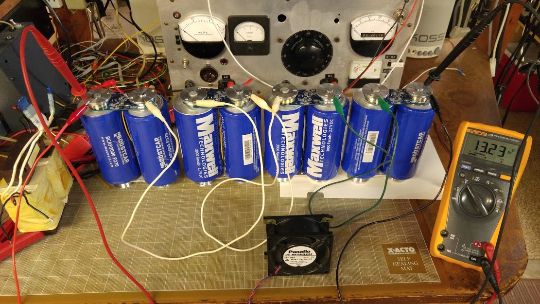
While six caps (6S) should be sufficient, we'll use 8S for our initial trials to allow more headroom. Here we put the 8S array into a plastic toolbox, along with a relatively small 12V SLA battery to keep the caps charged.
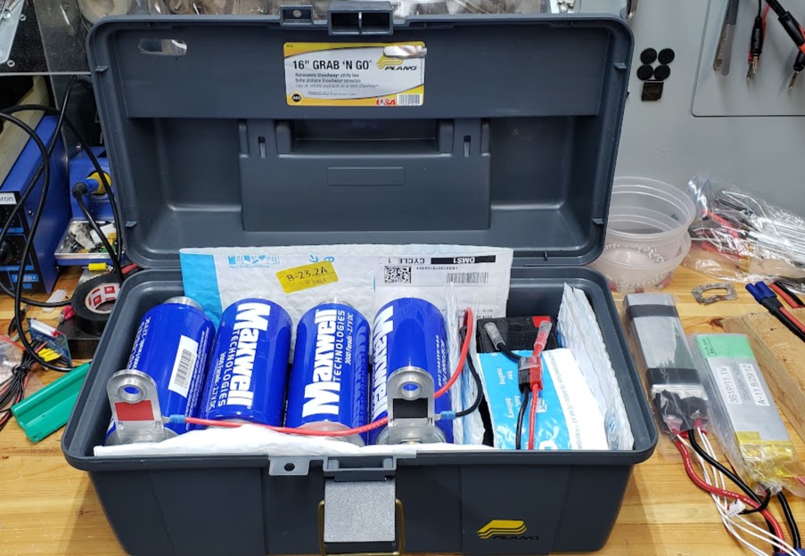
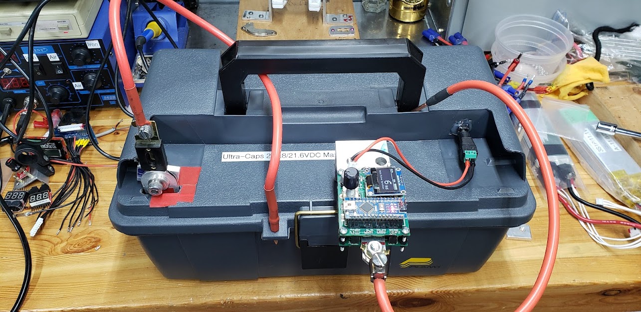
The caps' positive and negative terminals are brought to the outside of the toolbox where we'll attach the Malectric's spot welder with the least amount of electrical resistance in the supply lines as possible. To assure a steady supply of current to the spot welder's Arduino-based control circuit, we'll tap directly into the SLA battery in the toolbox.
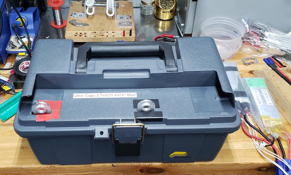
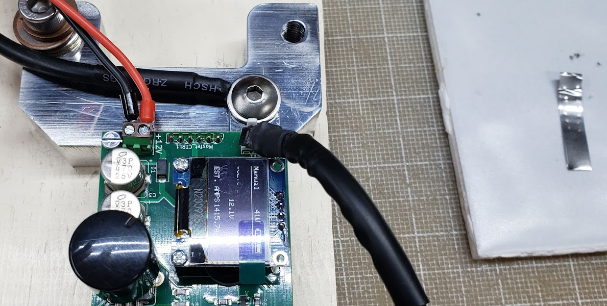
Photo showing completed electrical connections with the v3 Malectrics spot welder mounted. Power cables have been kept to a minimum, with 1/4" thick aluminum stock used to mount everything directly to the super-capacitor binding posts. The controller unit is powered directly from the 12V SLA battery inside the box via the 5.5/2.1 DC power jack connector in the lid.
We decided, however, NOT to 'pull the trigger' on this power supply/spot welder combination -- yet -- see the following section.
Marc Schoenfleisch is the designer of this spot welder and is the head of malectrics.eu, the company supporting it. According to Marc, the controller of this spot welder does *not* limit the amount of current (amps) that flows through the welding probes and the work. The controller only controls the time (in milliseconds) during which all available current flows through the probes.
This means that the total amount of power (amps*volts*time) going into each spot weld operation is dependent entirely on the power supply being used, the total amount of resistance (milliohms) in the entire probe circuit, and the duration of the pulse as set by the controller. Given enough available current (over 800 amps), coupled with sufficiently low circuit resistance (low number of milliohms), there is a high likelyhood of exceeding the ratings for the controller's MOSFETs and the TVS protection diode(s). Magic smoke is a likely result.
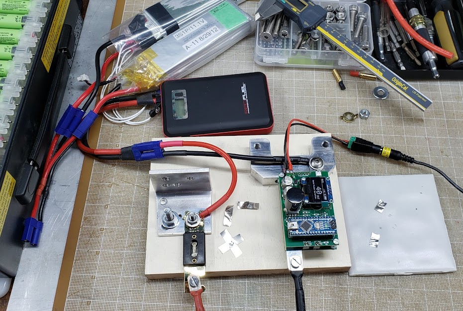
Until we can determine with reasonably accuracy the number of amps that will flow using the supercaps supply, we'll be using a current-constrained supply whose boundaries we're familiar with. At the moment, this is a 3S2P lipo pouch pack, and an 'emergency car starter' pack supposedly capable of 200/400 amps. Initial tests suggest that both supplies are marginal, requiring more than 40ms times to get reasonable welds. Even at 60ms there isn't really good penetration, and at those 'long' weld times the work starts to get hot. Our supplies need a bit more 'punch'.
After doing some more research, Denny and I decided that due to the estimated milliohm ESR (effective series resistance) of the eight supercaps in series, combined with the supply wiring and connectors, we'd be unlikely to exceed the maximum current ratings of the Malectrics welder's eight MOSFETs and four TVS protection diodes. To damage the board we'd have to exceed 1,000 amps for a fairly long time. If we started with the 8S supercaps charged to a relatively low charge of 10.5 volts and kept the weld time to 1 ms (millisecond), we could see by the resulting weld -- or lack of it -- how many amps the 8S array was producing. It's also important to remember that when you combine capacitors in series, you are giving up capacitance (farads). While gaining voltage potential by multiplying (2.7x8=21.6V), you lose capacitance in similar fashion (3,000/8=375F). The available energy for each weld is thus based on 375 farads at 10.5 volts. As it turns out, it failed to penetrate the 0.15mm nickel strips, leaving two barely visible marks. We know we need to have substantially more than the 200 amps we estimate that we were getting from the nine year old lipo packs and the 'emergency car starter' packs, but not more than the 1,000 amps that the Malectrics spot welder can handle.
This shows some of Denny's 'back-of-the-napkin' math to determine the series resistance involved with different power sources used to drive the spot welder.
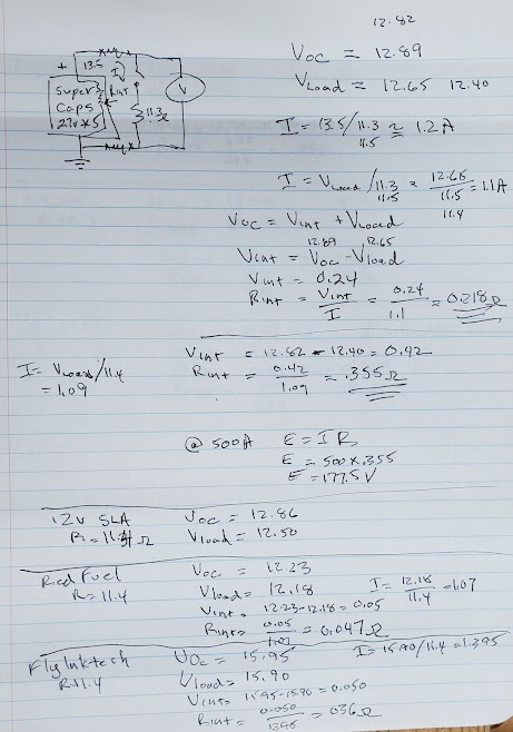
As an interesting aside for currently (Jul 2021) available AI technology, the following text is what Google Lens recognized in the photograph above. The text is shown with no edits.
The next step was to increase the available capacitance, and if appropriate, also the voltage. The most direct way to increase the capacitance is to lower the number of capacitors connected in series (see explanation above). If we went from 8S to 4S, we would effectively double the available capacitance from 375 to 750 farads. The above calculations supported the idea that using the 4S supercap array would not damage the unit, but would certainly tell us whether we would have enough power available. The smaller number of caps also reduced the allowable voltage to 10.8 (2.7x4), but that was fine since we'd be running the controller from a separate 12V wall-wart type power supply for this experiment. What we learned was that 750 farads worth of supercaps charged to 10.8 volts provided more than enough power to do effective welds at 1 millisecond. Since this resulted in almost no effective control over pulse duration, we needed to reduce the amount of input power.
We were going to jump directly to 5S, which would give us 600 farads at up to 13.5 volts. However, Maxwell, the manufacturer of the supercaps, doesn't recommend or support odd numbers of series connected supercaps when using their balance/protection boards, which we are. This leads to using a 6S configuration, which gives us 500 farads at up to 16.1 volts. Since we're limiting ourselves to 13.5 volts to remain below the controller's maximum voltage, our available energy will be 500 farads at 13.5 volts. The effective number of amps going into the weld will now be determined by the total resistance in the welding circuit, including the power supply, cables, connectors, probes, and the work itself.
Here we convert the supercap array from 4S to 6S. Note the dim glow in the 12V automotive light bulb (from my 1957 Karmann Ghia) which is being used to safely drain the caps. Whenever you work with supercaps, you really don't want them to be charged to any voltage due to their ability to instantly weld anything conductive that touches both positive and negative contacts.
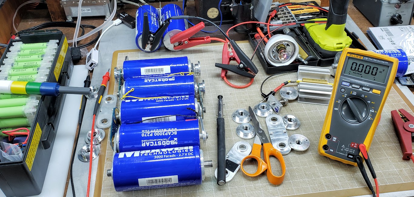
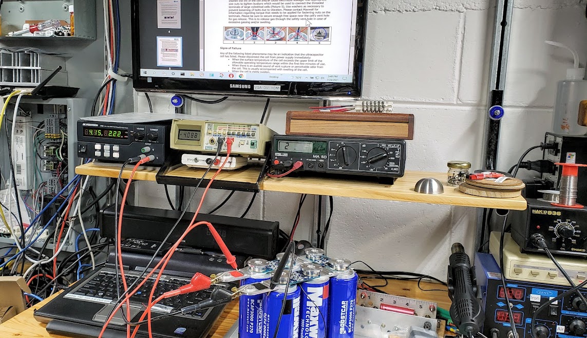
After reconfiguring the supercap array to 6S, we use a CC-CV bench power supply to recharge it to about 11 volts, at a conservative 2.22 amp rate. We could be safely doing this at the bench supply's maximum 10 amp rate without harming the caps. We picked 11 volts, well below the 14 volt maximum rating for this spot welder. Since we're also well below the 16.1 volt maximum of the 6S supercap array, there was no activity visible on the caps balance/protection boards.
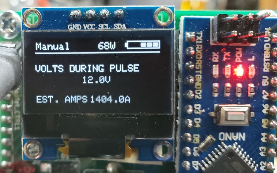
Using the v3 welder, connected directly to the 6S array, we get an estimated 1,404 amps per weld. This reading will be too high since the controller's estimate is based on the 12 volts of the separate supply being used to power the controller at this point. The actual welding circuit is operating at 11 volts and below. The results are shown below.
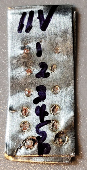
Here we see a two test strips of 0.15mm pure nickel strips welded together at 11 volts and less than 1,400 amps. We're getting acceptable penetration even at 1 millisecond, and there would be no need to go over 3ms. By 6ms, we're nearly blowing through the nickel strips. The next step is to reduce the number of amps going through the circuit so we can have a bit more granularity in the ms adjustment range. Most users of this unit report weld times approaching 20ms when spot welding 0.15mm nickel strips to batteries. We'll do this by adding more resistance into the power supply side of the welding circuit to reduce the number of amps. We'll also go back to powering the controller circuit from the same supply used for the actual welding. This will hopefully give us more accurate current readings.
We switched to the v4 unit and added several feet of stranded 10AWG cables to the positive and negative sides of the welding power supply circuit. One cable was copper, one was aluminum, because that's what was handy. After beginning the test welds again at 1ms, we finally got near-perfect results at 10ms. Definitely in the right ballpark now. The controller's estimated current was off by even more since by now the supercaps had dropped to less than 11 volts, and we're powering the controller with lipos at 12.1 volts.
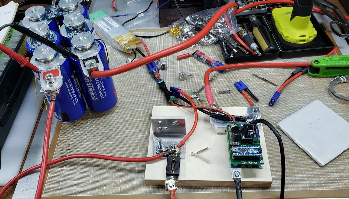
These two test strips show the even gradation of weld penetration going up from 1 to 15 milliseconds. Adequate welds can be achieved well before we get to the 15ms setting. Based on these results, we're likely getting more than 600 amps of pulse power per weld. These welds were done using the 6S supercaps not being recharged, so the starting voltage of 10.8 volts dropped slightly after each of the 15 welding operations. The controller was being separately powered at 12.1 volts.
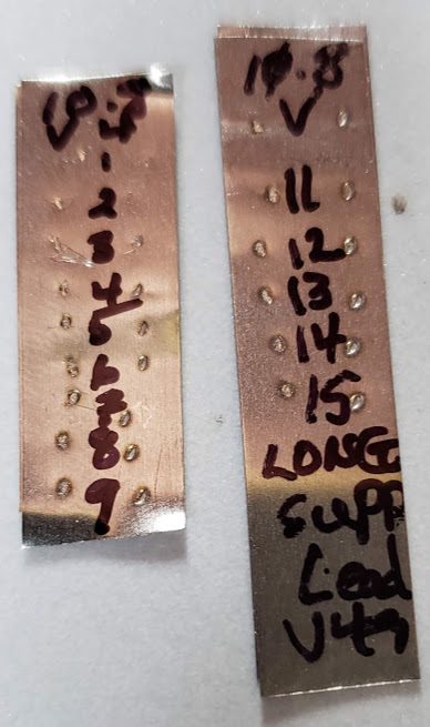
This look at the v4 estimate of 1,415.7 amps being used is clearly too high. The error is likely due to the difference between the controller operating voltage of 12.1 vs. the probe circuit welding voltage of 10.8 (or less). We will modify the setup so that the controller's power is drawn from the supercaps, and they in turn will be kept charged via an attached SLA battery.
Because the controller is limited to 14 volts max, the SLA cannot be charged to more than that. We will limit the available welding amps by modifying the ESR of the probe circuit as needed to put the pulse duration into a range allowing reasonable adjustments (10-20ms).
Return to Top of Page Return to Main Menu
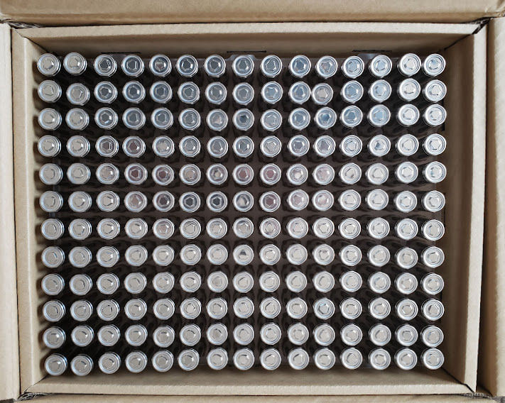
No, this is not going to be a Tesla EV battery that will be used to power a bicycle. It's a project that uses 180 "Unused", but not "new", Panasonic lithium ion cells purchased from BatteryClearinghouse.com (BCH). They were advertised, in April of 2022, as "Like new Panasonic NCR1865J2 3400mAh 18650 High grade cells". The description includes the statement that "These are re-wrapped Panasonic cells" and that "they are testing above new grade and we are guaranteeing them at 95% capacity!" My initial testing puts them closer to 93% (3,166 mAhrs) of their original rating (3,400 mAhrs), but at a cell price of ~ $2.50 delivered, it may just come down to variations in testing methods. I'll continue to build several packs and see how they hold up in real-world use.
Showing the top of the 180 cells packed in the box within a box, which was packed within a box.
Some claims exist that these cells were originally manufactured for use in Tesla electric cars. In this project, the goal is to build several modules using these cells that will be charged by onsite solar panels and also used to assist with bicycle-based transportation. In order to maintain flexibility for using them both in the small solar (12/24V) and biking (48V) world, I'm going to assemble the modules in a 7S6P configuration. Each 7S6P module will thus operate in a nominal 25 volt (3.6v x 7 = 25.2V) mode. Assuming a real-life yield of 3,100 mAhrs for these 'tesla' cells, each module should provide [25.2V x 3.1A x 6P] 468.72 watt hours of energy. Rounding this off, each module would be rated at 0.47kWhrs of energy.
For biking use, I'll combine a minimum of two modules in series to make a 50 volt (14S6P) pack, yielding 0.94 kWhrs of energy. Assuming an assist consumption of 10 watt-hours per mile of travel, two modules would allow a trip of 94 miles.
For longer trips or pulling a heavy trailer, I'll combine four modules to make a larger 50 volt (14S12P) pack good for 1.88 kWhrs.
For solar use, they can be used in either 24 or 48 volt systems, depending on which controllers and or inverters are used. Non-commercial scale solar installations tend to be either the small 12/24 volt battery systems used for RVs and boats, or the larger residential systems using 48 volt backup batteries. Since I haven't yet settled on which side of this fence I'll land on, this battery design approach will allow either system to be used.
After ordering 'lego-style' plastic battery holders from BatteryClearinghouse (BCH) and test-assembling a 7S6P pack, I decided to CNC single piece cell holders instead. I based this on being able to have a structurally stronger pack while still being light-weight, and leaving me more options to use the cell holders as part of the final pack structure. This shouldn't be confused with Tesla's "structural pack," which makes the pack so rigid that it becomes part of the vehicle's structure. Also, the bare cells were a very loose fit in the plastic cell holders and would have required hot glue to stabilize the pack. I did use the 'standard' cell center-to-center spacing of 21.2mm (0.7955") used by the interlocking cell holders so that I could use the pre-cut nickel 'fuse' connecting sheets, also from BCH, for the electrical connections to each cell's positive terminal. During the first pack's construction, I managed to inadvertently 'test' the fuses by shorting several rows of cells together. Who knew that masking tape could burn so quickly?
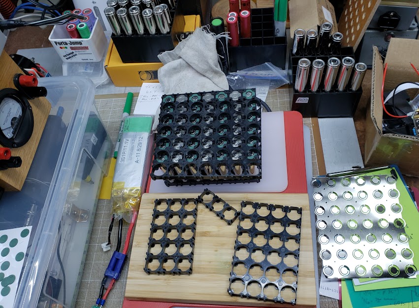
Using the JPods CNC system (VCarve is the design layer) makes it easy -- and predictable -- to get a good fit for everything. Trial and error, plus scrap pieces, is a requirement for my engineering style.
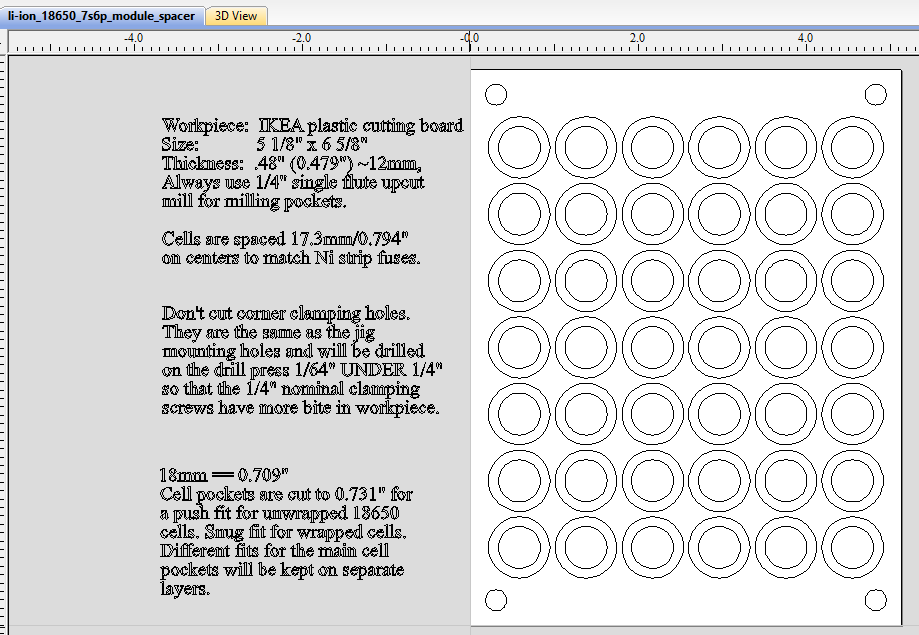
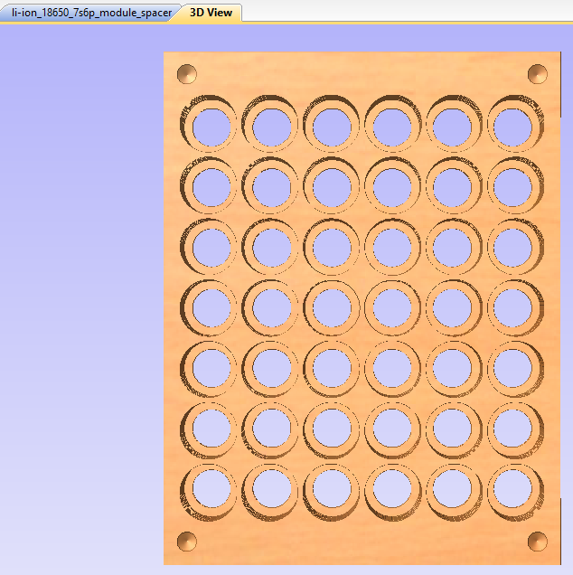
This shows a 3D preview of what the above design will result in. This stage doesn't replace trial and error, but it helps to show that you're in the right ballpark. The cells are kept from sliding out by thin 'shoulders' left in each hole, which trap the cells when the top and bottom are pushed on. These non-conductive shoulders are also critical to avoid shorting out the cells when nickel strips are welded to the cells' positive terminals -- which are dangerously close to the negative terminal of the cell, which is the entire body of the uninsulated cell. It's extremely important to be careful with anything conductive near the positive ends of these cells.
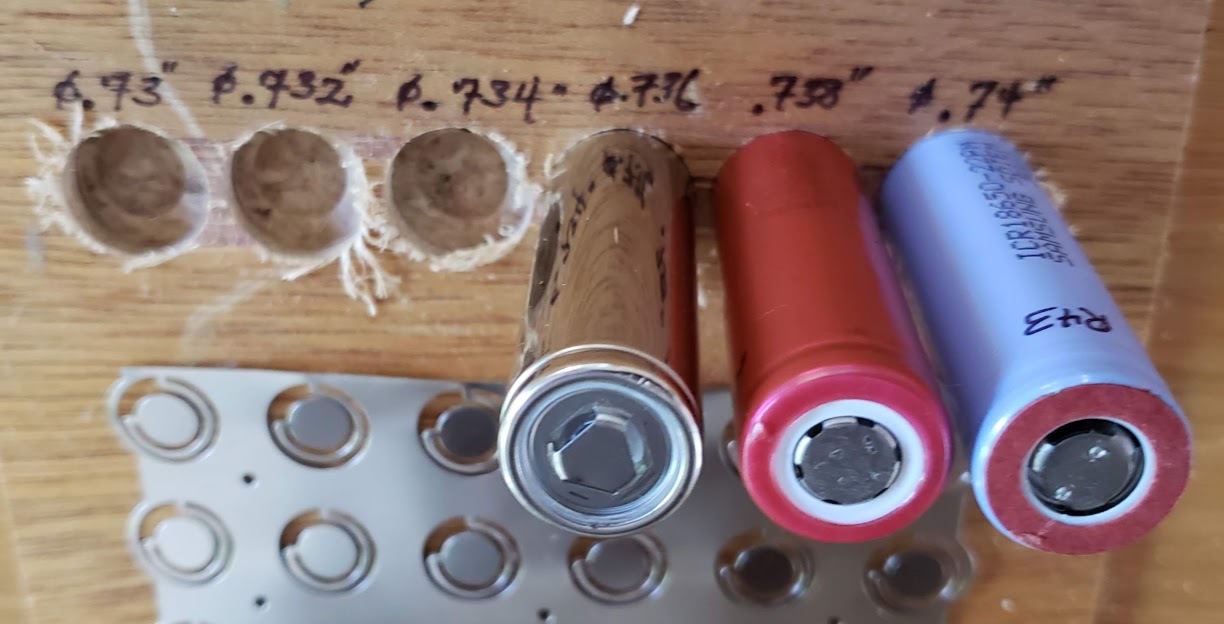
After experimenting with several hole diameters, I picked the 0.731" size as the ideal push-fit for the bare 1865J2 cells I'm using for these packs. This is not the 'true' dimension of the pocket holes, but the nominal size I'm using for the HandiBot CNC machine with a 1/4" single flute upcut bit installed. The HandiBot is very accurate in its positioning and repeatability, but the actual hole size depends on the accuracy of the size definition of the bit being used.
This is a complete mockup done in premium 1/2" plywood. The unwrapped 18650 cells can be easily pushed into the holes, but will neither wiggle nor fall out when the holder is tipped upside down. When the entire 42 cell (7S6P) pack is pressed together, it should be structurally sound.
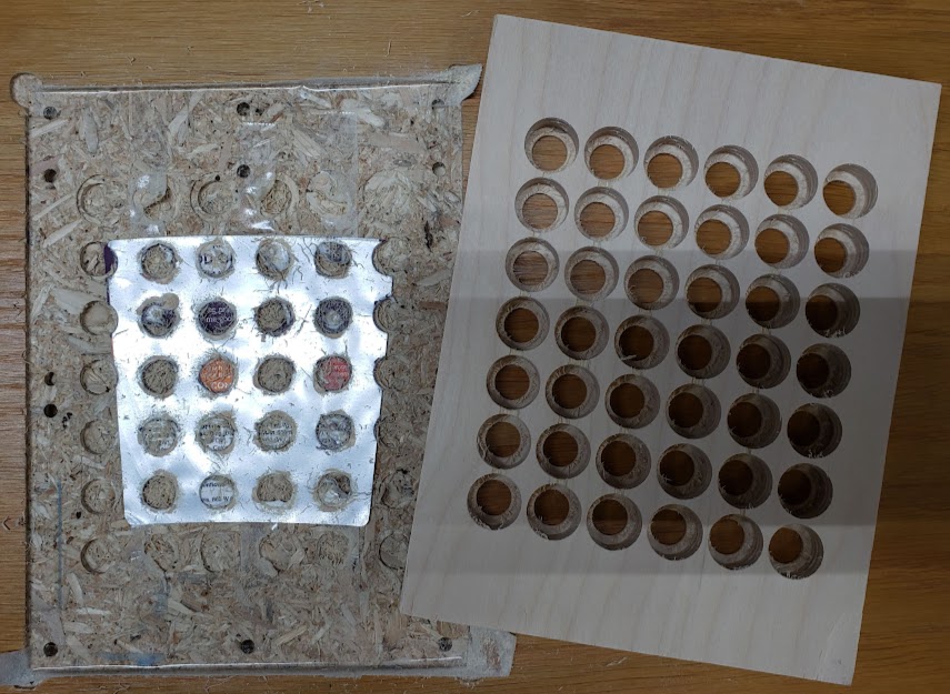
I next tried doing this using IKEA's bamboo cutting boards, but it turns out that they aren't really viable due to the nature of the fibers in the material. There is a tendency for the material to rip apart under certain conditions, which makes CNC milling unpredictable. Experimentation led to using HDPE plastic cutting boards instead, with ~12mm (~0.5") thickness being optimal. The Ikea boards are a bit thin, so cutting boards from Costco were used for the final production version (see below). Of course by the time in mid-2022 that I was going into production, Costco was no longer selling them.
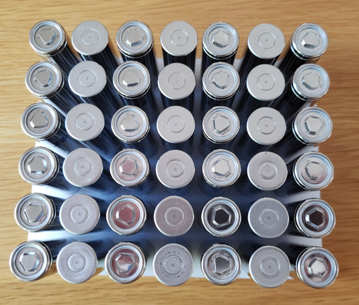
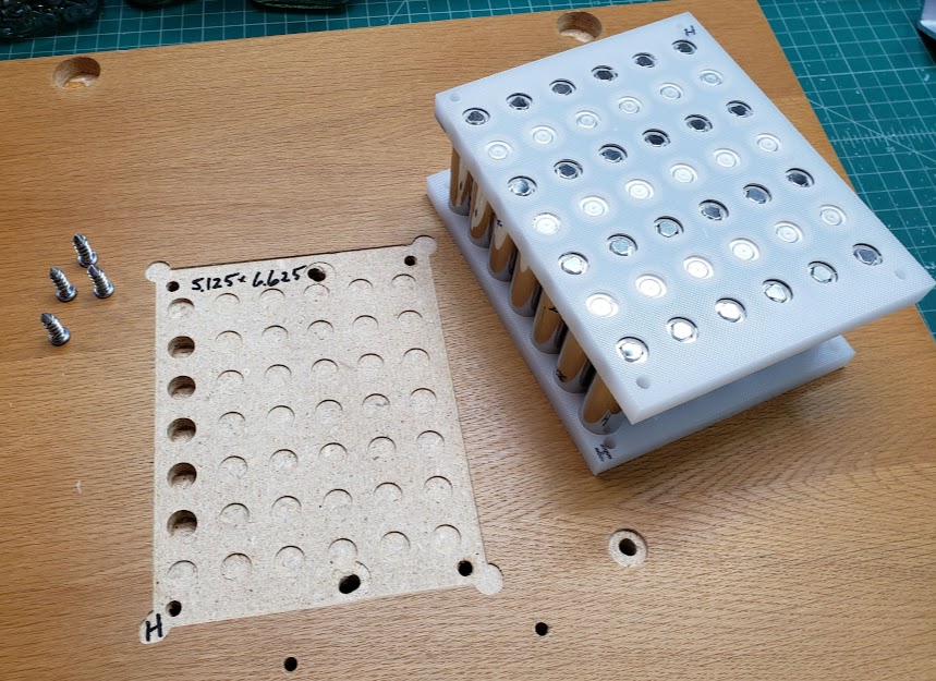
Next we see the completed cell 'sandwich' as well as the CNC jig used to firmly hold the plastic blanks, sized at 5 1/8" (5.125") by 6 5/8" (6.625"). All cells are spaced on 17.29mm (0.794") centers to accommodate the 'standard' nickel strips with built-in 8 amp fuses. These fuses were designed to fit the 'lego' style plastic battery spacer/holders commonly available. Published reports I've seen put this dimension at 21.2mm (0.8345") on center, but this was too large for the nickel strip I obtained from BCH. The four corner 1/4" holes are 0.3" inside their corresponding edges. [This first production sample shown here is actually using the 21.2mm on centers spacing.] Collectively, there is enough friction among all the cells and the plastic to keep the sandwich firmly connected without undue pressure on any particular part of it.
Return to Top of Page Return to Main Menu
Overview of the workbench on which the electrical connections are being done. The techniques used are very common for cell-based pack assembly as this is being done in early 2023. More information about the DIY spot welder seen on the bench (in the grey plastic toolbox) can be found elsewhere on this page. The pack on the left already has the nickel strip connectors spot welded in place, while the pack on the right is waiting for this part of the assembly.
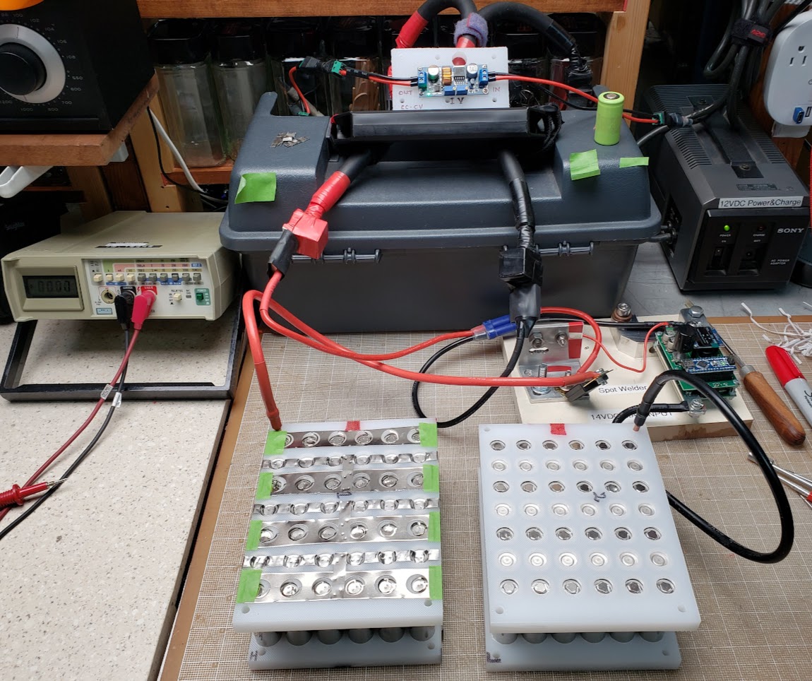
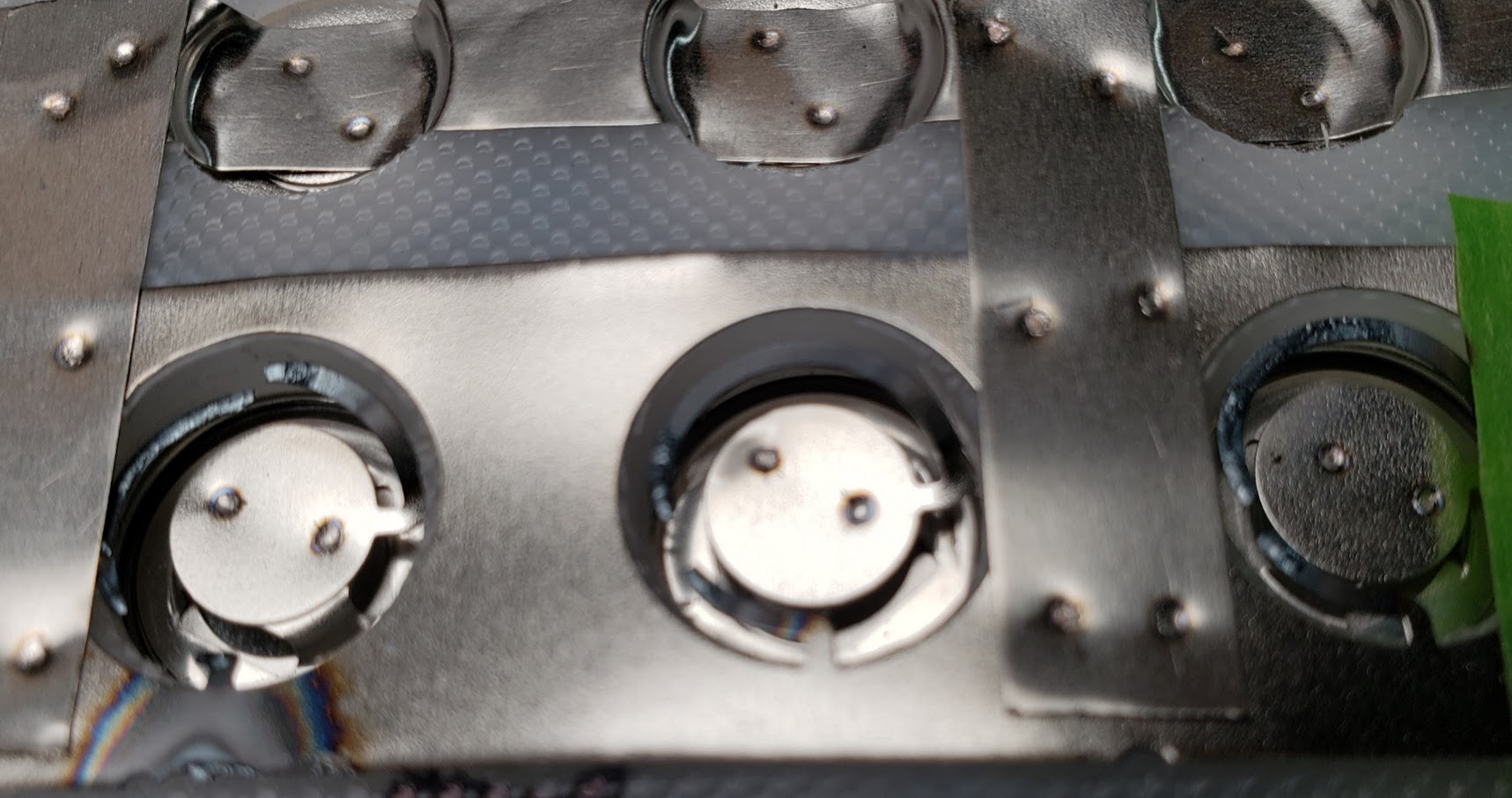
This shows a closeup of the pure nickel strips (0.015") welded to the positive and negative ends of the cells. The positive ends of the cells are connected via individual 'fuses,' which are merely very narrow strips of nickel in a circular shape. Since all current leaving each cell must pass through this narrow strip, an excess of current -- in this case approximately 8 amps or more -- will cause the strip to heat up until it glows red and then finally melt. I accidentally dropped a strip of nickel on top of this pack, shorting out two parallel rows of cells, and the results are visible.
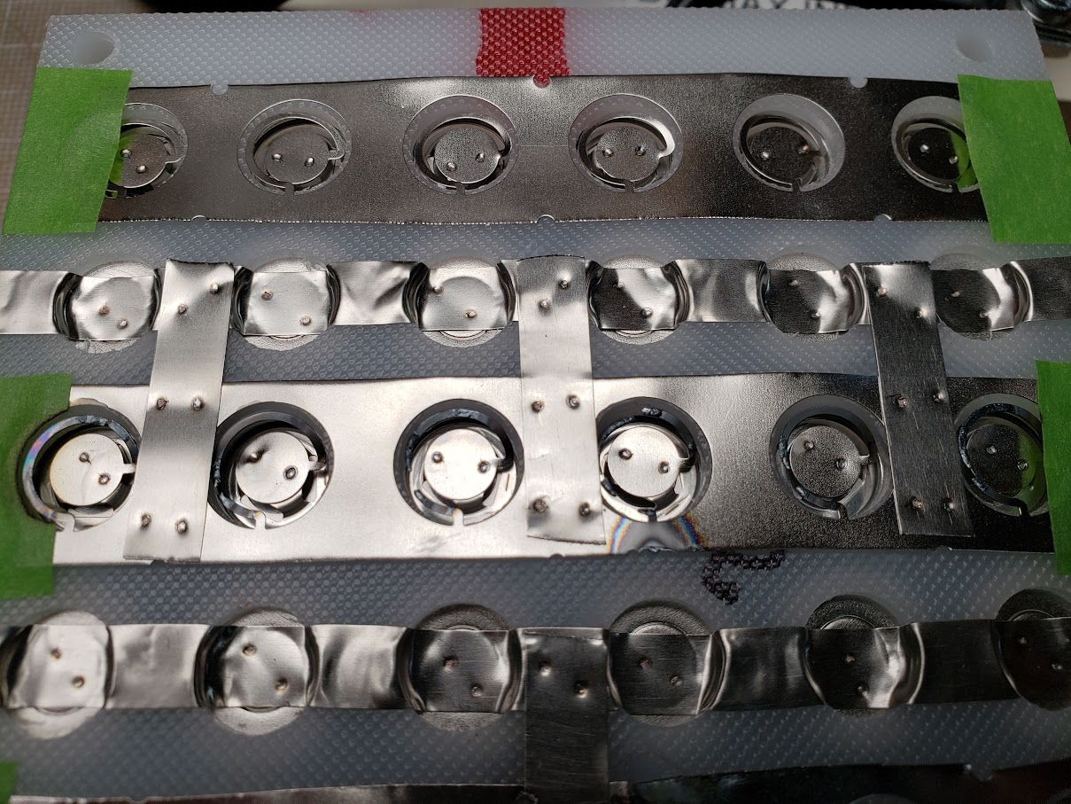
This is a closeup of the strip with the blown fuses.
Return to Top of Page Return to Main Menu
We have settled on using 14S/52V lipo batteries in "Hailong"-style cases, with their corresponding battery mounting plates. Because this format is based on a fairly standardized case and mounting mechanism, it allows us to easily swap out the batteries between vehicles, as long as each vehicle has been engineered to accommodate one or more Hailong compatible mounting plates. This battery case is likely manufactured generically in china and sold by multiple vendors under their own brands and labels. The following shows the battery marketing brochure used by the vendor "Unit Pack Power" (UPP) from whom we have usually purchased these batteries.
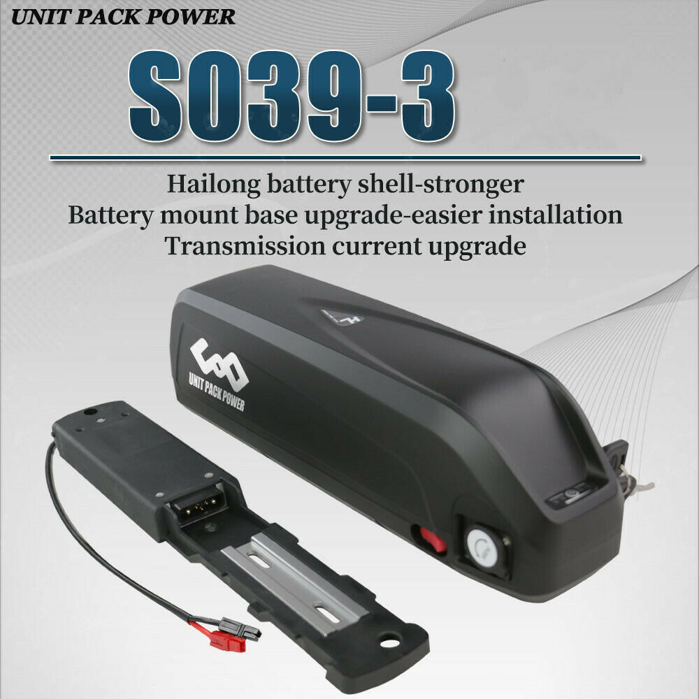
There are a variety of sizes, and at least two different connector pin types. The exact specifications of this particular battery can be seen in the photo below.
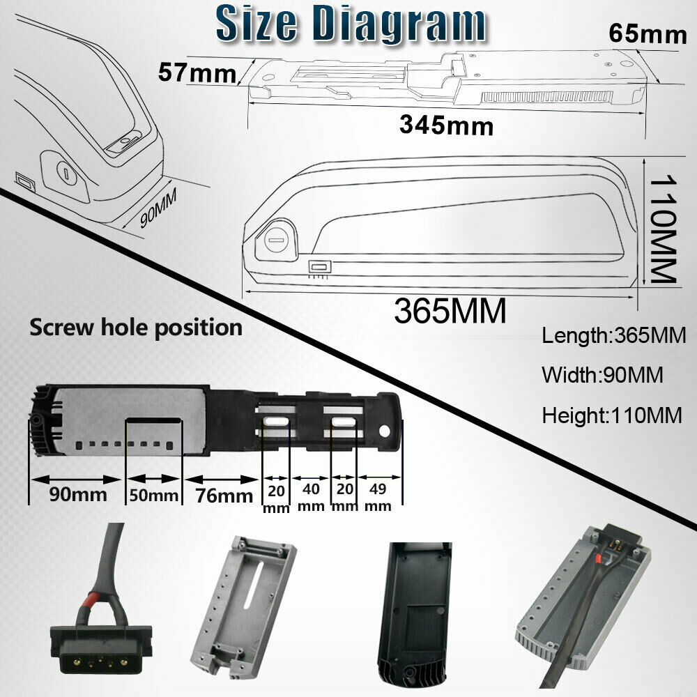
Note that the electrical connector used in this battery has five(5) round pins. It's important NOT to get the batteries or mounting plates that use the flat 'blade' style connectors, even though it's possible to convert one type to the other, if the appropriate parts were available.
This is what the battery looks like when shipped from vendor "Unit Power Pack" in china. When ordering more batteries compatible with this series, note the "SO39-3" model description. The "SO39" (uppercase letter O, not zero) describes the physical case, while the "-3" designates the use of the round pins connector.
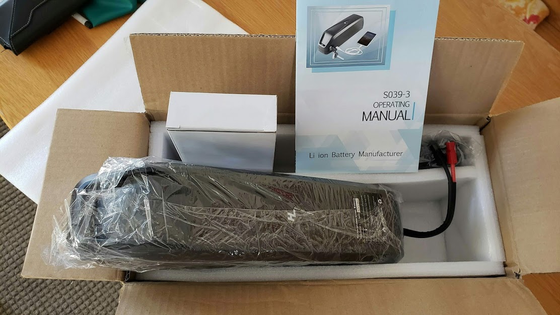
Also seen in the above photo are our preferred red and black Anderson PowerPole plugs used to connect the battery to the controller.
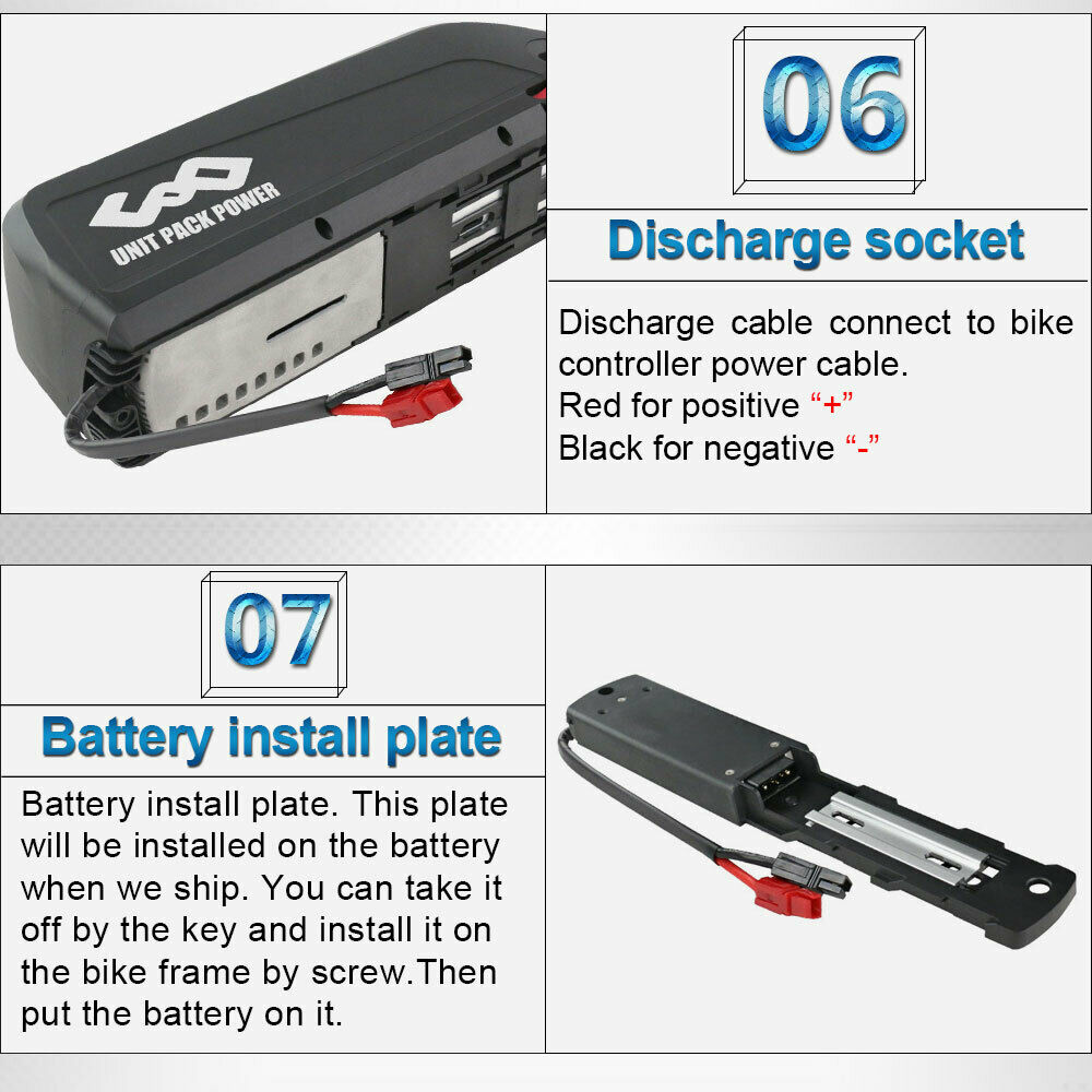
The battery's mounting plate is attached to the vehicle and stays there. All electrical wiring exits the thicker end of the mounting plate. The two holes seen in the lighter (aluminum) middle section are spaced so as to be compatible with standard bike waterbottle mounts.
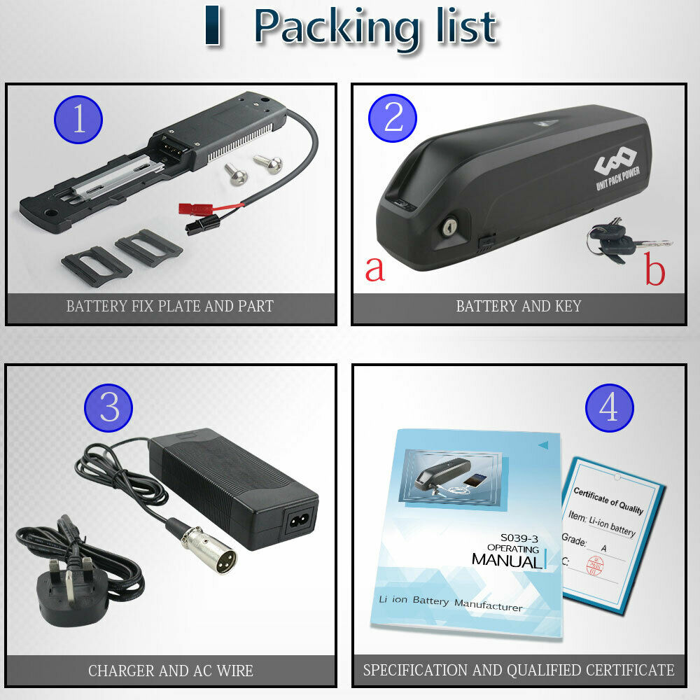
Of the following options for the battery's discharge leads, we prefer the "small" Anderson PowerPole connectors. The vendor should attach the red plug to the positive and black to the negative, but it's worth checking before plugging things in. These batteries come with a built-in 'soft switch' which allows connections to be made without risking sparks. When we need to plug in a battery without this switch, we use an adapter that incorporates an XT-90S plug (on far right side of image). That plug (female side) has an integrated resistor to 'preload' the capacitors in the controller, avoiding the sparking.

To actually buy one or more of these batteries, google the string "hailong SO39-3 battery" and take your pick of whatever vendor appeals to you. The cases are all the same, but some vendors will fill it with "premium" (non-Chinese) 18650 lipo cells, which will result in higher cost batteries. Unless they make a big point of it, they'll be delivered with the cheaper Chinese cells, which are probably good enough for what we're doing. Just be aware that genuine Samsung cells, for instance, cost twice as much as no-name cells.
Return to Top of Page Return to Main Menu
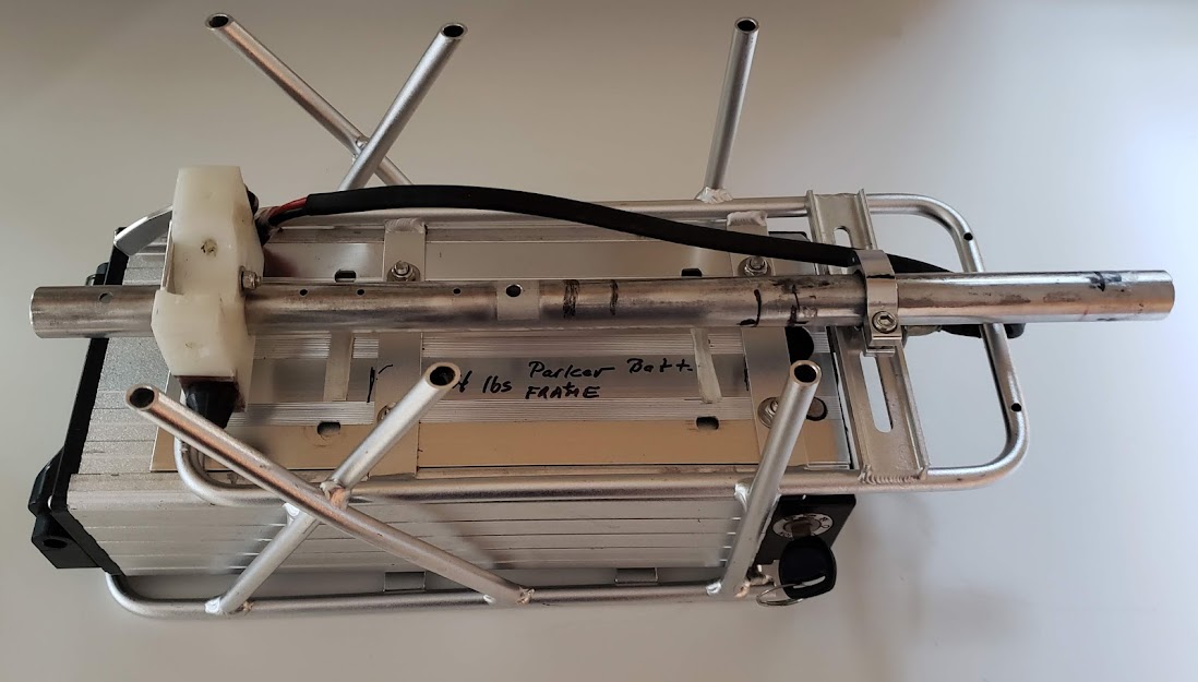
This battery & charger originally (Feb 2019) came to us as an unknown quality item via craigslist, along with a geared front wheel hubmotor and K-type controller and display ($400). It's called the "Parker" battery now because it's named after an intermediate owner of the battery after its ebay sourcing. The factory charger connects to the battery's 'RCA' style DC charging jack, but now most charging is done 'bulk' style via the Anderson powerpole output connectors. When charged this way, energy comes from the solar panels via the DC-DC converter, using the CC-CV method with the high voltage cutoff set to 58 volts. The cells must be of decent quality because this pack delivers a solid half-kWhr of energy with very little voltage sag in the 0-30 amp draw range. Per its label, the battery is a 52V/12Ahr/624 Whr pack, and we've gotten 595 Whrs (95% of new rating) out of it before triggering LVC. Because of its separate charging port, it likely has a BMS inside. In the photo below, it is shown mounted in the DIY battery rack for Stella. We knew it was 14S because of the voltage characteristics and guessed that it was 6P due to size and weight calculations. This was finally confirmed in Mar 2023 when the battery was disassembled for cleanup and maintenance.
The Parker battery on the Mickelson Trail in SD (May 2022) with Deb in the foreground and Chief Crazy Horse in the far background.
[The battery pack on Deb's bike is the Hailong SO39-3 described in detail in the section above.]

One day this Parker battery is powering my StreetMachine through the Black Hills of South Dakota, while the next it's powering our dumpster-dive lawn mower in Minnesota. The 14S6P/52V battery is perfect for powering the 48V motor that came with the mower. That and a sharpened blade make quick work of the grass that was growing while we were out biking. The fact that the same solar energy that made the grass grow in the first place is also being used to cut it should qualify for some kind of apt expression?

Starting on the last day of Mar 2023, this battery was disassembled for cleanup and maintenance. While we don't know its year of manufacture, we do know that this pack is at least four years old and has gone through numerous charge/discharge cycles. The cells themselves may be labeled with some kind of date code (we did find this later, see below). Everything was working fine, but the plastic end containing the ignition switch and the charge port had suffered physical damage and was partially cracked, with small pieces missing. This had allowed some moisture to get inside the pack, and the corrosion process had begun.
This photo shows the Parker battery with one plastic end cap removed. This is the end that has all the wiring coming out of the battery, as well as its BMS board. The thick blue wire is the common ground/negative of the pack, while the thick red and yellow wires are the switched positive power and positive charging wires. The skinnier yellow wire is the charging port's negative wire and is routed to the BMS inside the battery (not quite visible in this photo). The battery's manufacturer intended the battery to be charged via the 'phono' (RCA) style jack at a relatively low current (less than 5 amps).
The other end of the battery case had the carrying handle attached. There are no wires or other connections on this end. It really wasn't necessary to remove this end, but it makes it easier to push the cells out as opposed to pulling them out, plus the other end has the BMS attached and it's not a good idea to stress that board.
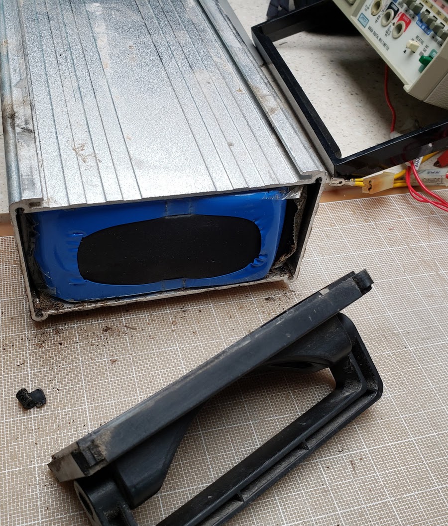
Once the ends are removed, the shrinkwrapped cells easily slide out of the aluminum case. This is not always the case, since many such battery packs have the shrinkwrapped cells glued to the case, making maintenance much more difficult.

The shrinkwrap (blue material on the left) is designed for a one-time use, so it will be recycled.
The greenish colored wax-like paper on the right is known as "fish paper" and is used to keep the electrical contacts of the cell ends (positive and negative) from shorting out against the case material. It can be re-used if still in good condition.
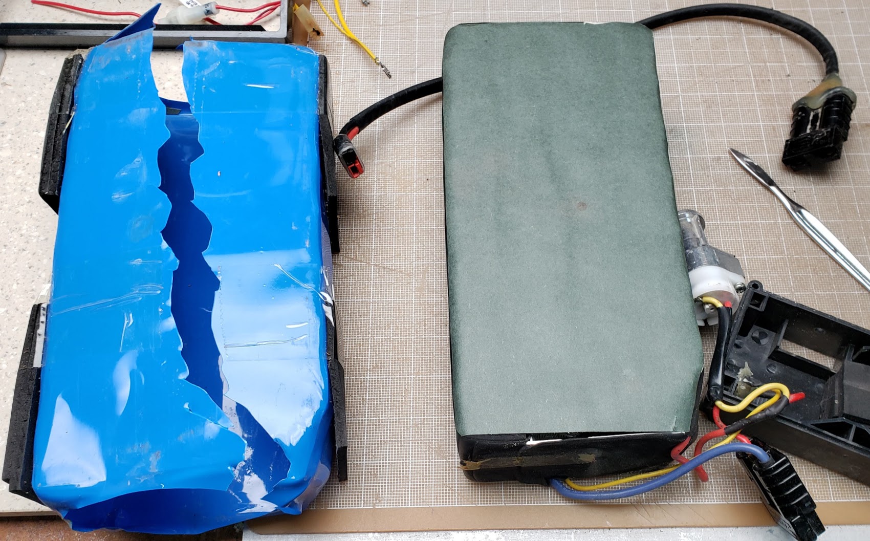
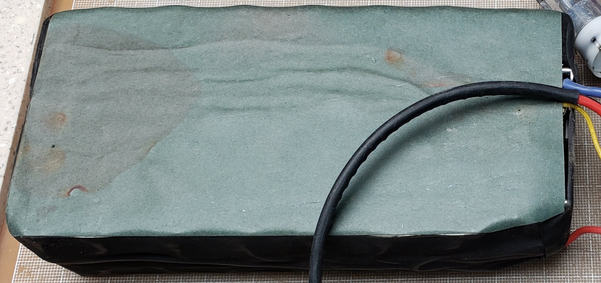
The fishpaper on the bottom of the pack at the handle end shows evidence of moisture ingress. Had this occurred on the other end where the BMS is located, this pack might have failed prematurely. Our experience shows that this is a common source of battery failures, but we might have gotten lucky on this one.
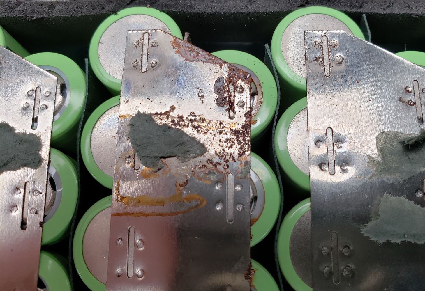
This shows the bottom of the pack with all 84 (14S6P} 18650 lithium-ion cells exposed. From the visible corrosion ("rust" in this case), it is obvious that the manufacturer chose to use the cheaper nickel-coated iron strips (instead of "pure nickel") to electrically connect the cells in parallel and series. It doesn't really limit the ability of the battery to deliver current, but it does make it more vulnerable to failure if not protected from the elements. Another example of Dick Cavett Emptor.
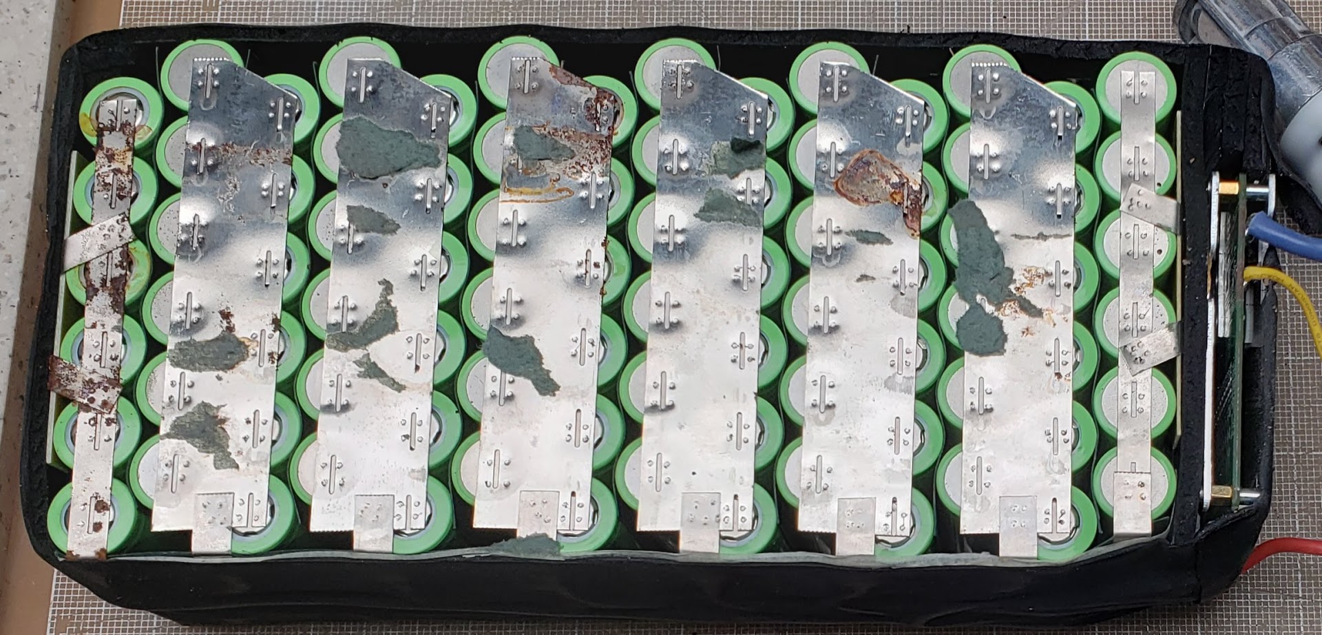
Closeup of the rusted spots. In spite of this, it seems this battery build quality is reasonably good up to this point. The spot-welds were clearly done by hand, but are well spaced and penetrate the material. The strips have enough mass to handle the practical maximum of 30 amps this pack is expected to deliver, and the connections have performed reliably so far.
All 84 cells appear identical, although I only peeled back enough protective layering to reveal the printed text on two of the cells. Both had the same model code "INR18650M", and the nominal listed capacity of 2,000mAh (2 amp hours). I'm guessing that the "20170502" may be a manufacturing date code for 2 May 2017. This makes sense based on the fact that we got this battery in 2019 from someone who had purchased it at retail and represented that it was relatively new. Since it doesn't specify a manufacturer -- at least not in any way that I can discern -- it's probably of 'generic' Chinese origins. I have no idea what the "NM17C13" or the "06" codes mean.

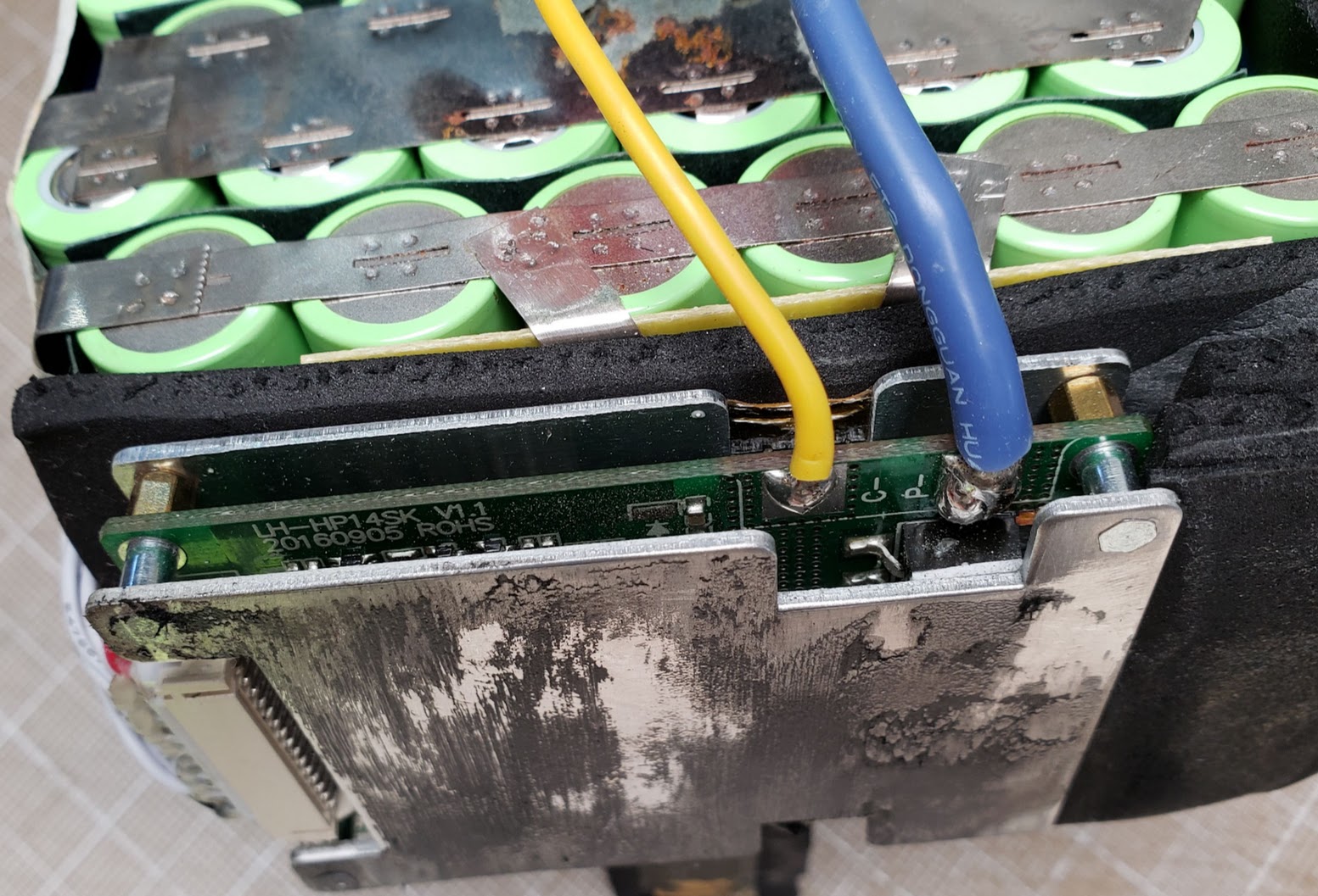
This shows the end of the pack containing the BMS (battery management system) printed circuit board and all of the load and charging wires. The BMS is specifically matched to the 14S configuration of the cells. Googling for "LH-HP14SK" (v1.1 model) results in an AliExpress board that looks just like this one and is described as "14S Li-ion/Lipo/LiMn battery protection board 48v(58.8V) lithium battery pack BMS/PCM 30A continuous Discharge US $13.58". The fuzzy black stuff on the BMS's aluminum heatsink is the remainder of the original black padding that was glued to it and is now cleaned off. I didn't have any known heat issues using this battery at up to 30 amps of draw, but it it's generally not good practice to 'insulate' heat sinks.
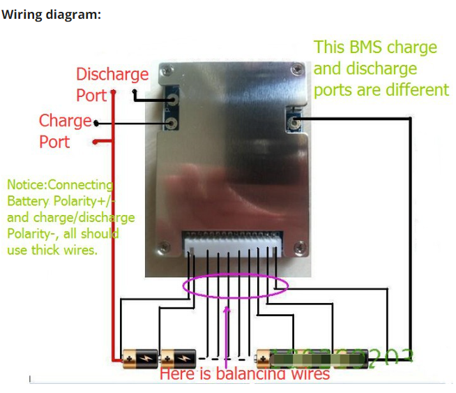
This is a screen-scrape of the wiring diagram on the same Chinese vendor's page referenced above.
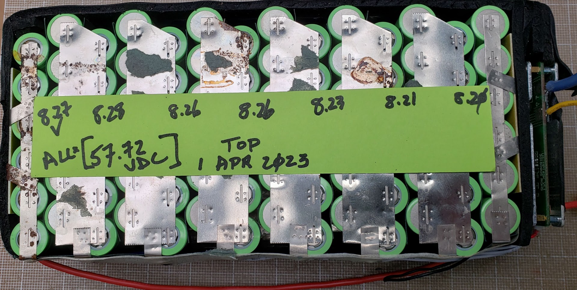
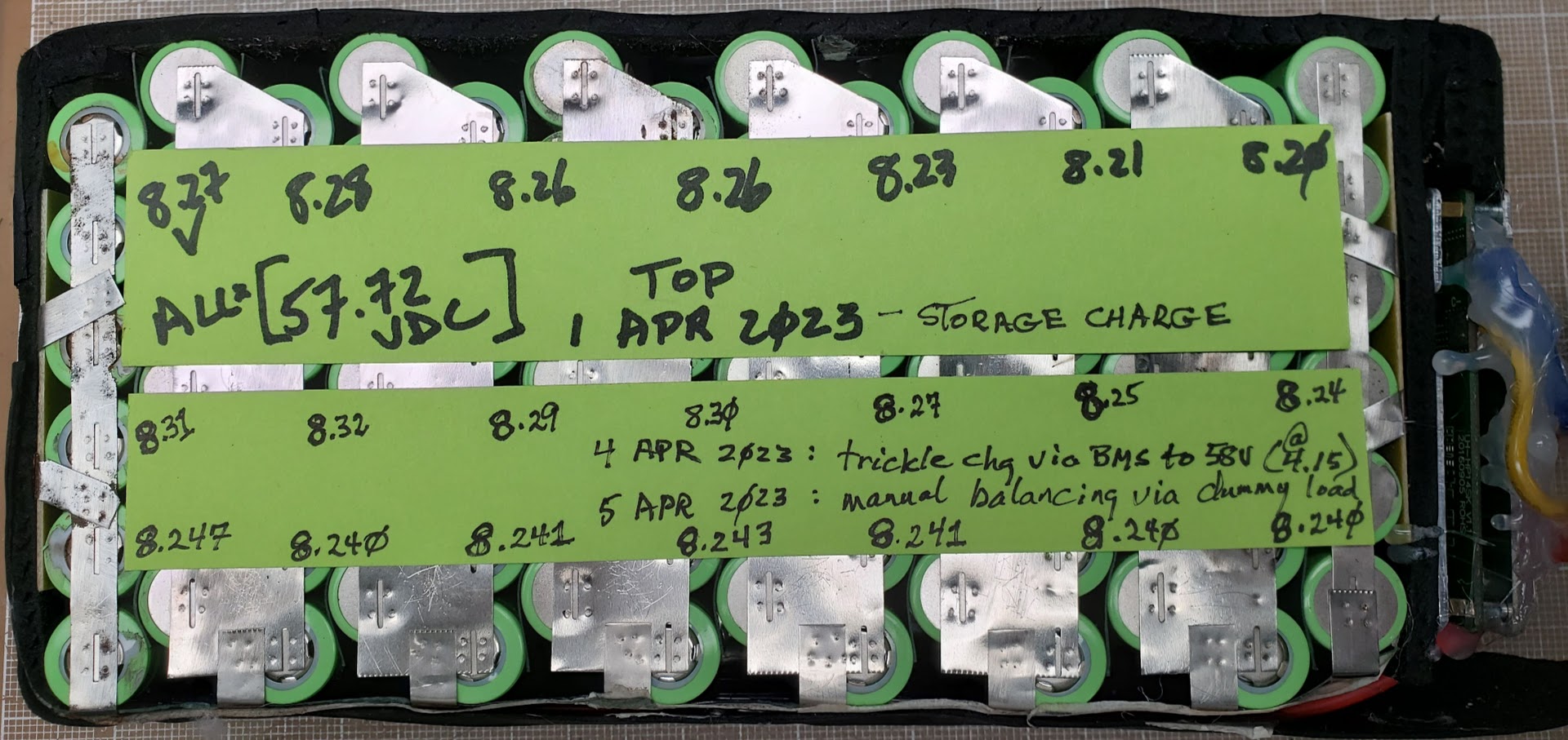
This pack has been sitting unused in a cool, dry environment for approximately four months, showing very low levels of self-discharge. The pack is also reasonably well balanced, with the 2S variation ranging from 8.20 to 8.27 volts (meaning the 1S variation is likely 4.10 to 4.135 volts).
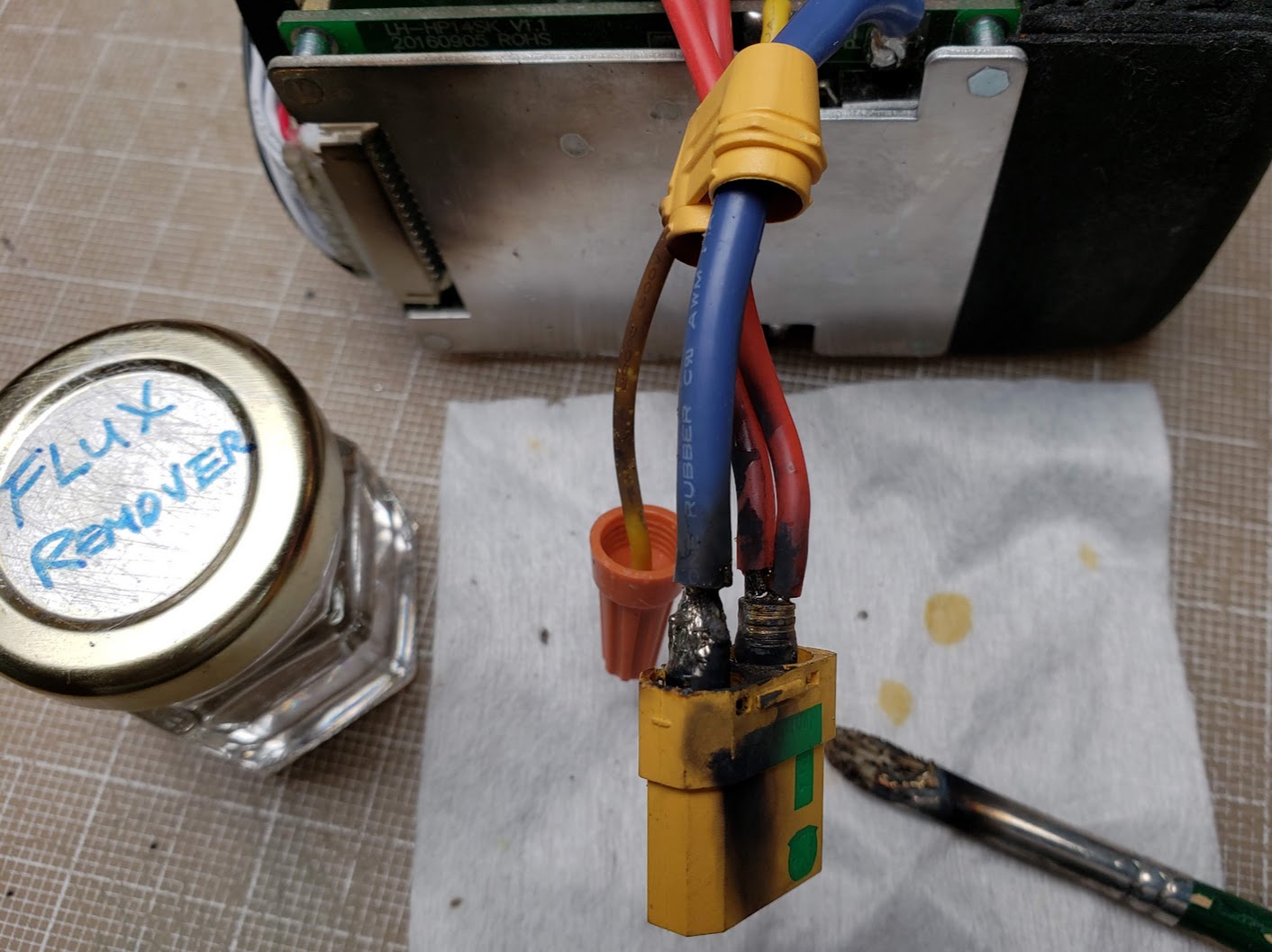
Did I make clear that you should *never* use any metal tools when working on a live battery pack? I replaced this pack's original (overkill) 120A PowerPole discharge port with an XT90S connector, which has the added benefit of having an anti-spark resistor built in. I used a small artist's brush to clean off the flux residue from the solder terminals. The chromed brass ferrule on the brush momentarily shorted the positive and negative discharge wires, resulting in instant fire, flames, and smoke. The flux remover likely contains alcohol, turning the brush into a caveman's torch. Note the soot deposited on the top of the BMS aluminum heatsink -- requiring *another* cleaning! I learned nothing from this experience that I didn't already know, so you can draw your own conclusions here. Also note the orange wire nut temporarily covering the end of the small yellow (soot covered!) wire. The purpose of this wire nut will become apparent in the next photo.
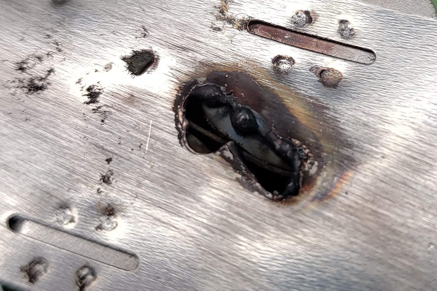
Speaking about learning nothing from experience, I left one flush-cut wire momentarily dangling without a protective end covering, and experienced another welding episode. This is not a result of a wire with exposed strands flopping around -- it was a silicone insulated wire cut with a sharp edge. To make contact with the nickel terminal strip, it had to touch it at an exactly 90 degree angle. I was simply too lazy to pick up and screw on another wire nut to protect against this (remote?) eventuality. Both of these 'fails' were easily preventable. I was lucky that no real damage was done this time, but it pays to remember that these batteries pack a LOT of energy.
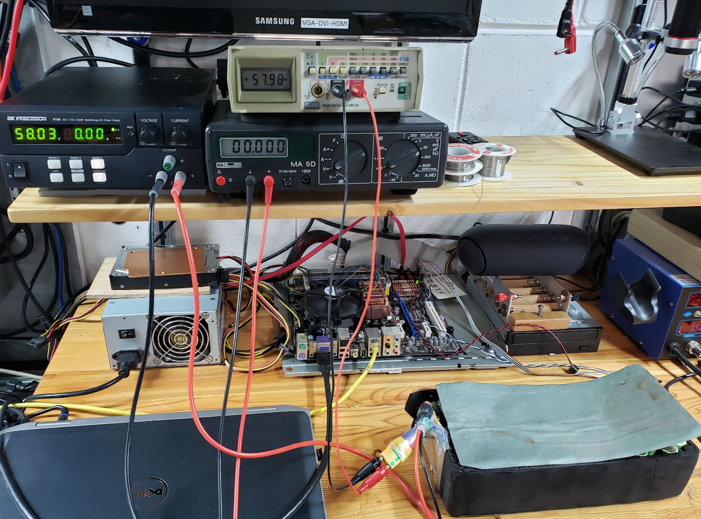
Before wrapping up the now cleaned up battery pack, it would be a good idea to balance the cells as much as possible. Many people erroneously believe that packs with a BMS are automatically balanced every time they are charged via the BMS. This photo shows this pack being 'trickle' charged (at 0.25 amps) through the BMS to a pack voltage of exactly 58 volts. This means that if all 84 cells in the pack were in fact 'balanced,' each cell's voltage would be at 4.15 volts (4.15*14=58.1). This charger (bench power supply) uses the standard CC/CV (constant current/constant voltage) method to charge this pack. I allowed this charge process to continue for a full 24 hours, even though it was actually done charging well before then. We will see in the photo following this one that relying on a typical BMS to keep the pack's cells balanced is not a good idea.
The voltage readings noted after the lengthy 'balance' charge process through the BMS show that the 2S voltages all went up by the same 0.04 volts (e.g., 8.27 to 8.31). Had any balancing occurred, the lower voltage cells would have received more of a charge than the higher cells, with the result that all readings would have been identical after a balance charge. An argument may be made that these cells are 'close enough' (8.24 to 8.31 volts, or 4.12 to 4.155 volts, if using 1S), and for most purposes they probably are. The point here is that the BMS is acting more like a fuse to protect the pack rather than a 'battery management system' that keeps the pack in balance. It is evidence like this that leads to the design of this battery's successor, the Tesla Quad bike battery, which will not utilize a BMS. This is not to say that packs shouldn't use a BMS, but rather that there may be other options to safely and effectively use an ebike battery pack without a (non-balancing) BMS.
The next step is to manually balance this pack, either by adding electrons to the low cells or removing electrons from the high cells. We'll remove electrons from the high cells by using the two Volkswagen Beetle 12VDC bulbs as dump loads, connecting them to the high cells until their voltage is identical to the lowest cell group (on the right side in this photo). Doing this is very time-consuming because the cells' voltages 'sag' when under load, and then recover slowly after the load is removed. It's definitely a hunt-and-peck procedure, and allowing plenty of time between spot discharging for the cells to recover. This tedious job really should be done by an effective electronic device -- maybe a BMS? (Yup, I know about "hobby chargers" that can do this -- search for "Revolectrix" on this page.)
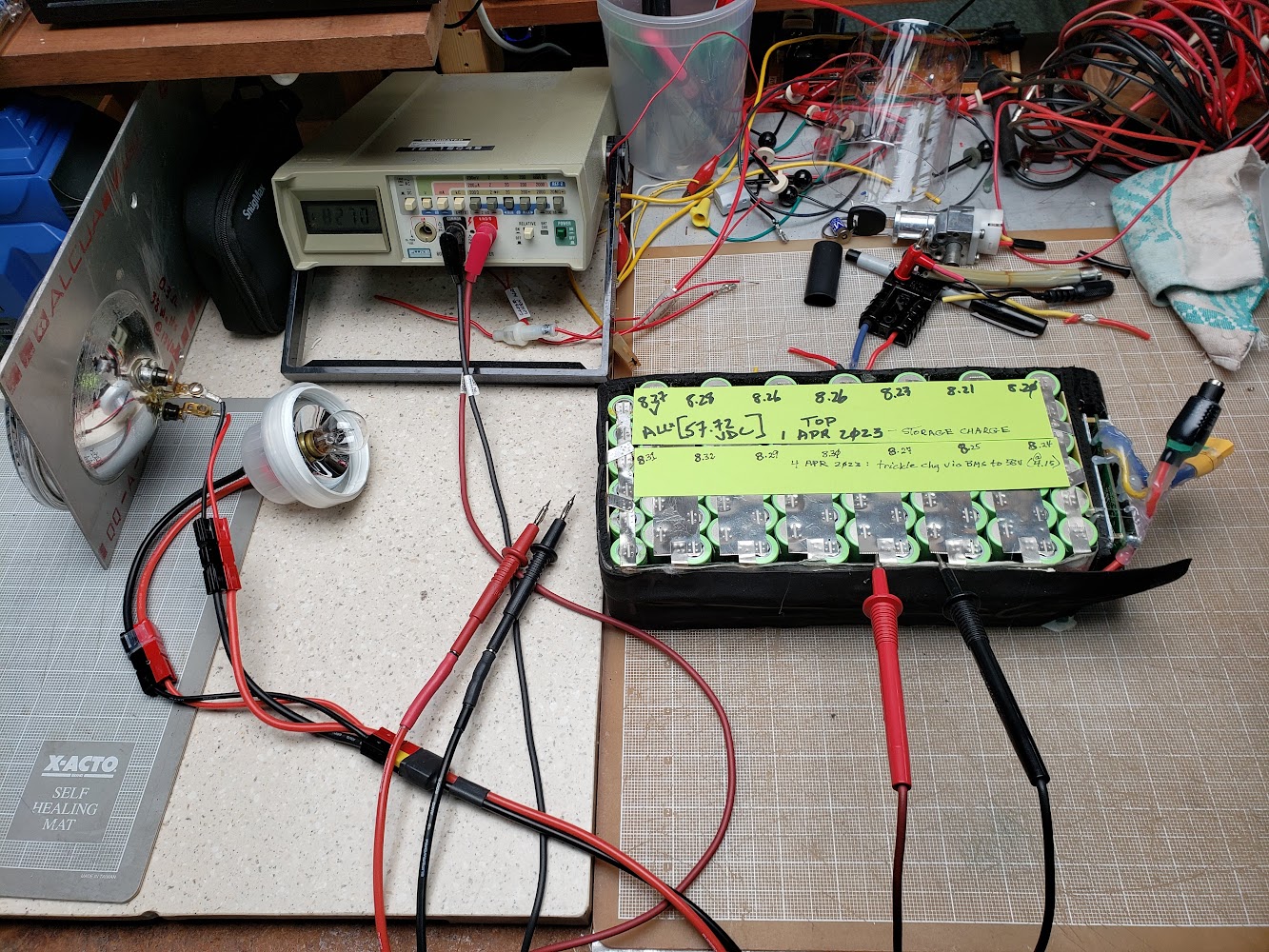
Not perfectly balanced, but close enough. The result is that each cell's charge level is very close to 4.12V, or somewhat below its maximum of 4.20 volts.
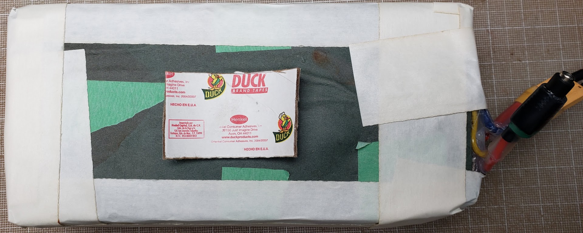
I'm not generally a fan of duct tape, but I didn't have the right size shrink-wrap available, so this will have to do.
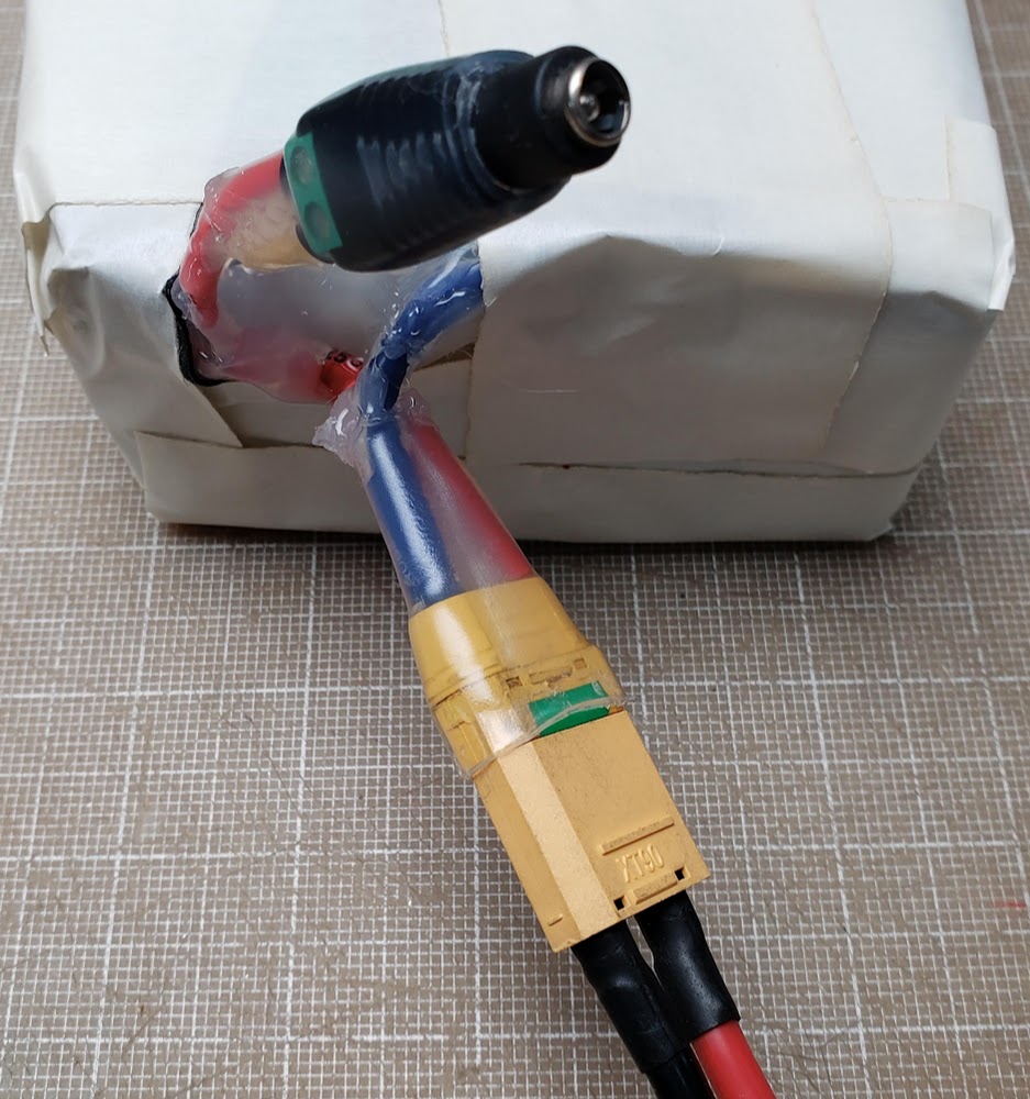
The original charge and discharge connectors have been replaced with a DC coax charge connector (pin positive, barrel negative) and an XT90S discharge connector. The charge connector is a 5.5mm/2.5mm ("large pin") type commonly used for medium to low power DC applications. The 2.5mm pin is slighter larger than the 2.1mm ("small pin") found in many very low current DC ("wall wart") chargers. If this pack is charged via the charge port (and BMS), the current will typically be no more than 2 amps, well within this connector's specs. If charged through the discharge port ("bulk charging"), the current will not exceed 10 amps.
The second layer is a commonly used shipping plastic wrap. Several overlapping, self-adhering layers result in a nearly waterproof protective shell.
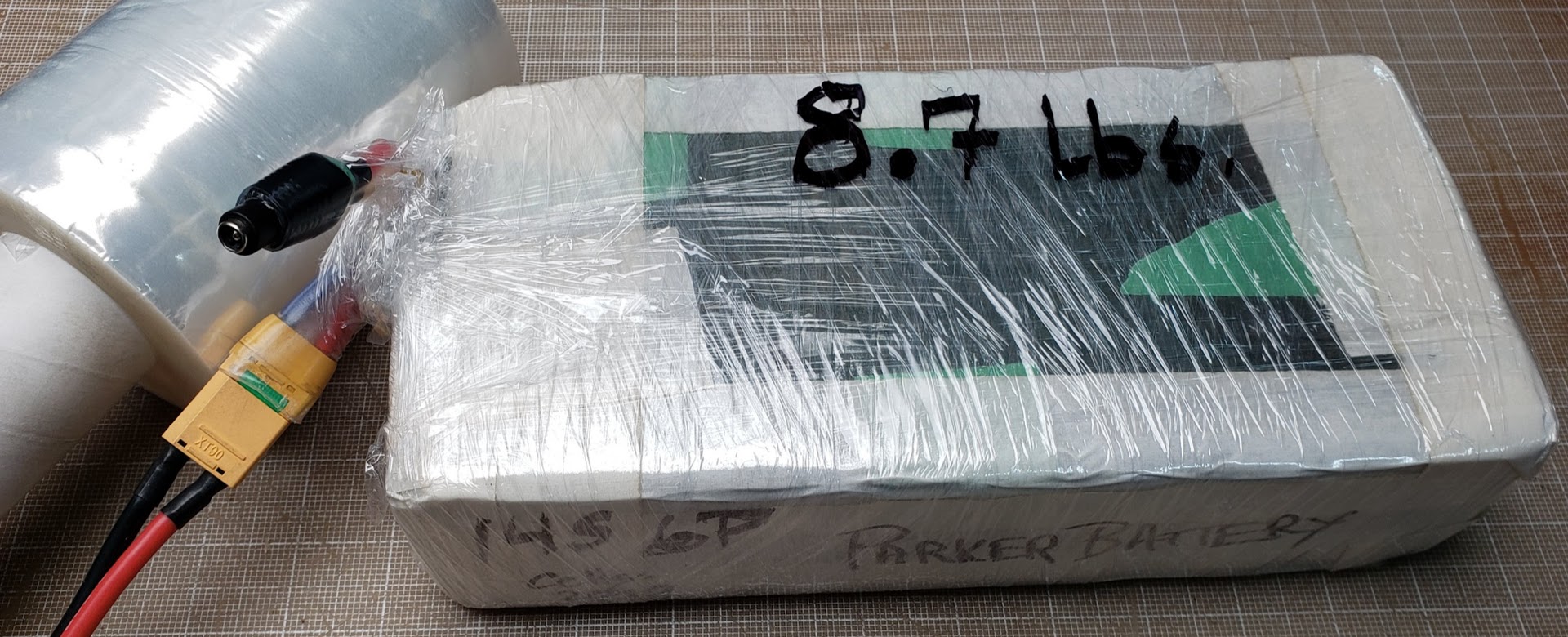
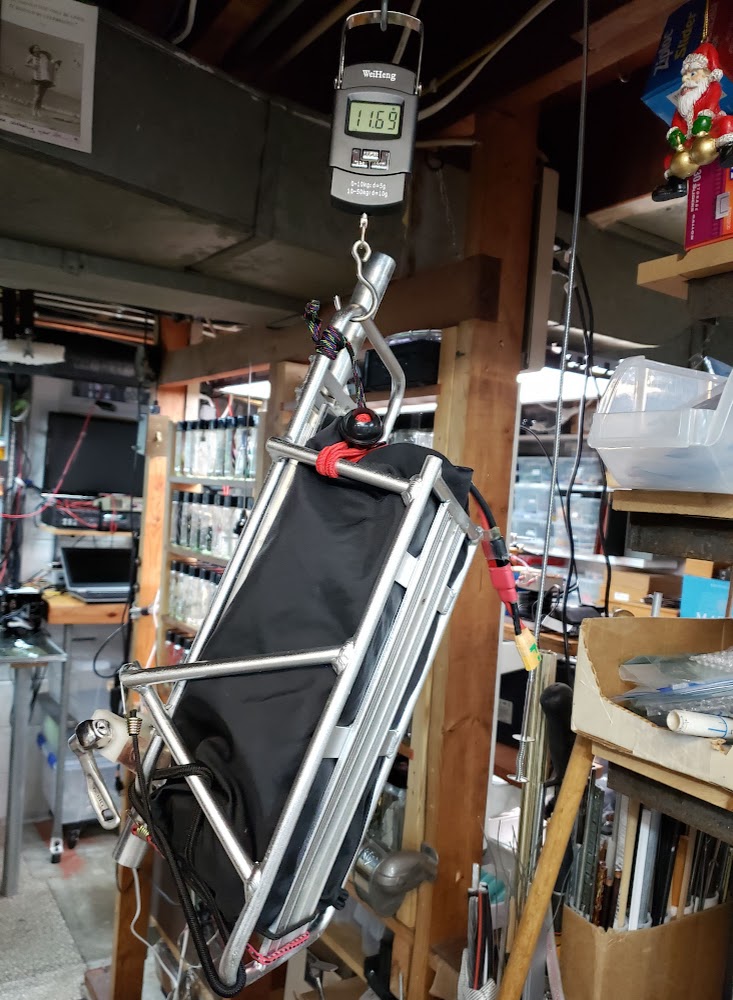
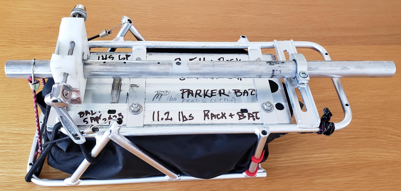
The final touch is to put the whole thing in a repurposed Marmot nylon stuff sack, allowing the outer layer to be easily laundered when it gets covered with road grime. The 8.7 pounds of the battery, plus the 2.5 pounds of the rack, plus the miscellaneous fasteners results in a total weight of 11.7 pounds, somewhat lighter than the original weight of 14.5 pounds.
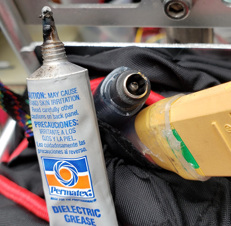
Did I mention that stupid failures come in threes? As a final touch to the pack before it goes back on the bike -- subject to all the springtime elements -- I thought I'd add a little protection to the exposed electrical contacts. Dielectric grease is a special type of grease that helps keep moisture from damaging contact surfaces while not significantly interfering with the flow of electrons. I leave it up to you to figure out what the "stupid failure" is in this picture.
... and it's now ready to ride.
Return to Top of Page Return to Main Menu
This pack consists of four separate 7S6P modules which are full-fledged batteries in their own right. When all four modules are connected in series/parallel for use on an ebike, the resulting Tesla Quad will be a 14S12P battery. It's called a "Tesla" quad because all 168 (14x12) individual 18650 cells were manufactured by Panasonic for use in a Tesla automotive battery. Acquisition of the separate cells began in April of 2022 and the detailed "build" process is documented at Building the "Tesla Quad" Bike Battery elsewhere on this page. The plan is to have this pack be put into service for the 2023 biking season.
Return to Top of Page Return to Main Menu
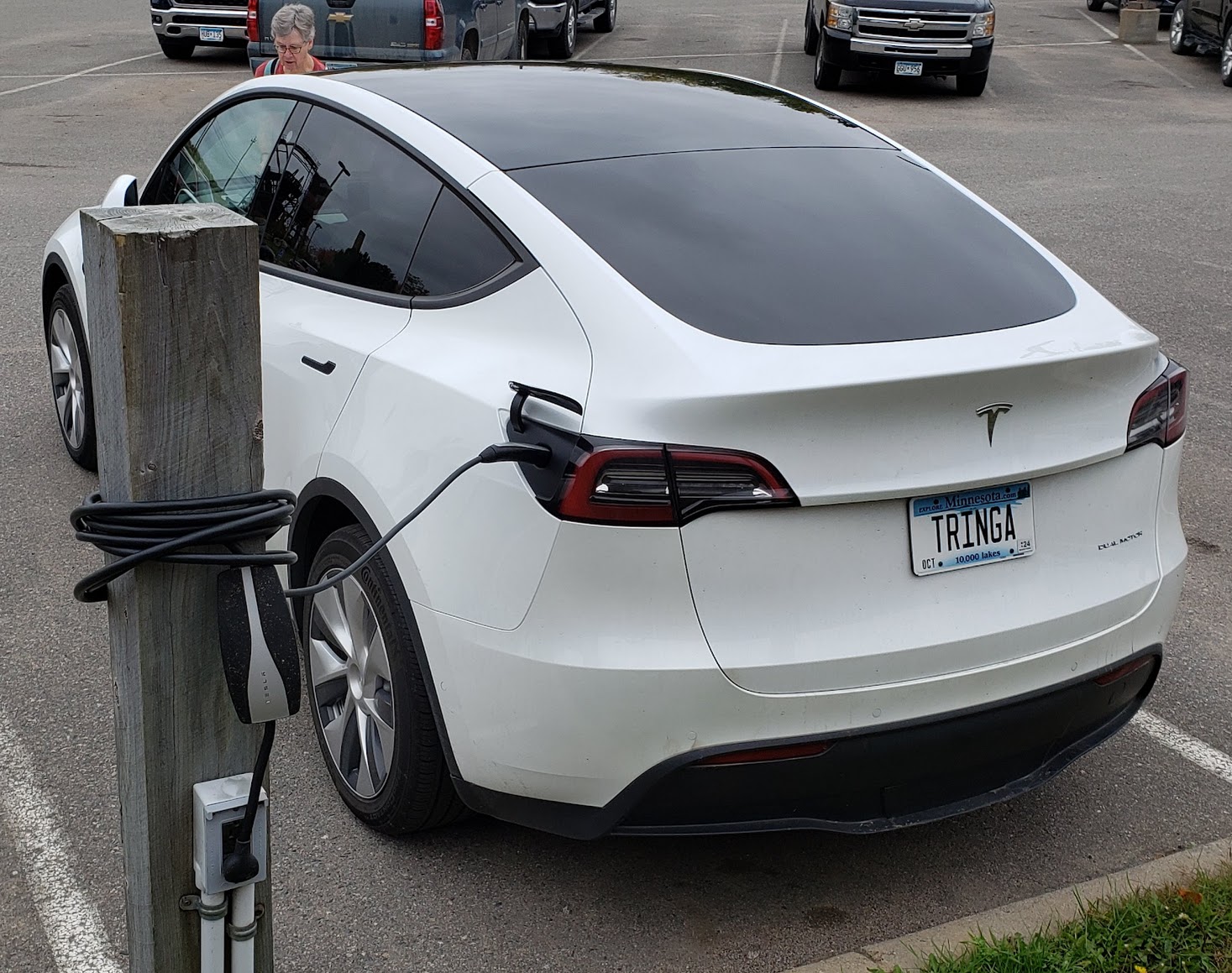
The Tesla Model Y Dual Motor/Long Range car is obviously not an LEV (light electric vehicle), but the battery it uses is mentioned here as a point of reference. Whereas the typical ebike battery has an energy storage capability of about half a kilowatt hour (0.5 kWhr), electric car batteries will have 50 or more kWhrs. This order of magnitude of 100 times greater corresponds to the energy consumption of the two types of vehicles. An ebike might use 20 watt-hours per mile while a relatively efficient electric car ("ecar"?) might use 200 watt-hours per mile traveled. If you're driving an eHummer, expect to use more like 400 watt-hours or more per mile.
This photo of a Model Y is shown recharging at a northern Minnesota lodge, far from any 'official' electric car chargers (in 2023). The charging outlet was originally mounted there so cars could plug in their electric 'tank heaters' to keep their engines warm in the cold winter months. This demonstrates the fact that there are a lot more electrical outlets in the world than gasoline pumps. Even gaining only 4-5 miles of range per hour of being plugged into a 20 amp 120VAC outlet can result in an additional 75 miles for an overnight stay. Staying several nights virtually guarantees that you leave with a 'full tank.'
Return to Top of Page Return to Main Menu
Back in the 'old days,' as they say, buying batteries (battery *cells* actually) was simple. You'd go to nearest hardware store or drugstore, or really any store for that matter, and buy whatever they were selling. You only cared about how many cells you needed and what size was right for your device. You'd buy several "C" or "D" size batteries for your flashlight and maybe a "9 volt" battery for your transistor radio. The brand would be either a Ray-O-Vac or Eveready, depending on what the store preferred to carry. If you bothered to 'test' them at all, you'd likely use something that was nothing but a glorified voltmeter. If your flashlight produced light and your radio played music, your batteries were OK.
Fast forward to the 21st Century...
I personally haven't bought a battery in a "store" since the neighborhood Radio Shack went out of business. I use rechargeable Eneloop (Panasonic) cells using NiMH chemistry for light duty items like remote controls and small portable LED lights. When they wear out after many years of use, Amazon brings replacements to my door. For larger tasks like powering my ebikes and lawnmower, I use battery 'packs' made up of cells using some form of lithium-based chemistry. Acquiring these packs, or the cells they are made up from, is NOT a trivial matter. By 2023, buying consumer grade packs at the retail level has become more convenient, but they are still much too expensive and too prone to failure. Both cost and reliability are improving over time, but not at the rate of other technology that we've come to rely on.
In order to make sure the cells you use will work for your intended purpose, you -- or whomever you get them from -- will want to "test" them to make sure they live up to their advertised potential. This is done not only to make sure that your device will perform as expected, but also to make sure that the cells are safe to use.
When we test cells, we are primarily concerned with their energy capacity, measured in milliamp hours (mAhrs), and their internal resistance/capacitance (iR), measured in milliohms (mOhms). Higher mAhrs are always better while lower mOhms are generally better. The whole issue of testing a cell's iR gets complicated very quickly and is beyond the scope of our efforts here, although we cover the basics in a separate section below.
We also visually look at every cell to make sure it isn't swollen or doesn't show any signs of having 'vented' any of its electrolyte. Any cell with signs of physical damage should not be used in an area or application where fire is not welcome.
Finally, some people use a cell's weight to verify its quality, with a higher weight for a particular cell being being a good thing. We have not (yet) put a lot of weight on this factor in our testing process. ;-)
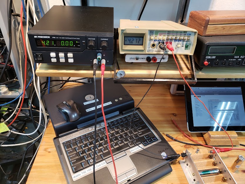
Before the cell's capacity can be tested, it must be fully charged. We use a lab-quality power supply that provides a constant current (CC) followed by a constant voltage (CV) until the current flow into the battery reaches zero, with the cell's voltage at 4.20 volts. The Fluke meter next to the power supply measures the voltage on the cell's terminals in the DIY charging fixture (bottom right). At the end of the charge cycle during the CV phase, when the current drops to 0.00 amps, the voltage momentarily goes up to 4.21 volts, as seen in the photo. The cell's actual voltage will drop a bit, typically to 4.19 volts, when removed from the charger.
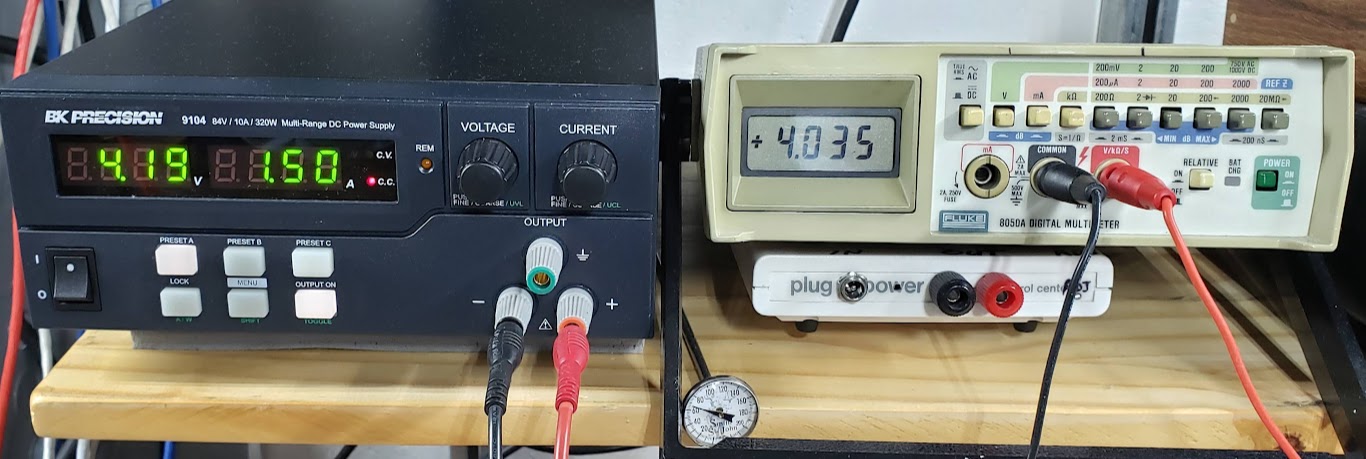
In the photo below, earlier in the charging cycle, we are still in the CC phase (here at 1.5 amps). Note that in order to 'push' this much current into the cell, the charger has to raise the voltage (pressure) to 4.19 volts. The actual voltage of the cell at this point of the charging process is somewhat lower, at 4.035 volts. This voltage gap between the charger and the cell continues to get smaller as the cell charges, and will go to zero when the cell is fully charged.
To test each single lithium cell's capacity, we use the ZH-YU ZB106+ v1.3 testing device, shown in use in the following photo:
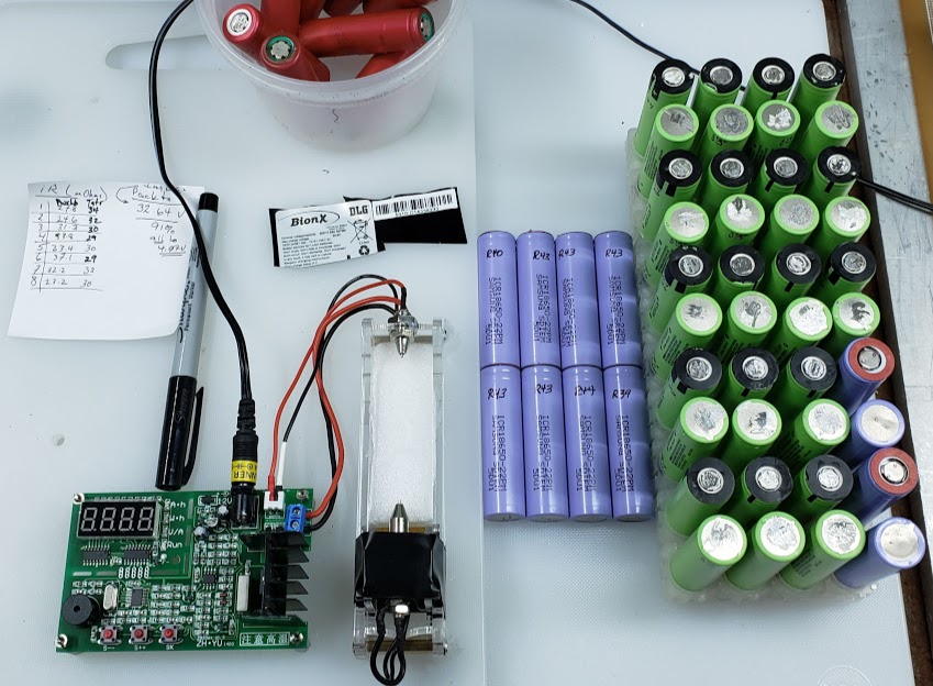
The actual tester is the item with the three red buttons and the digital display. The original instructions were in chinese, and the 'translation' to english (chinglish) accompanying the tester really only make sense if you already know how to use the tester. This translated version was "transcribed" to HTML by tom@mmto.org, and is available here: Tom's Electronics Pages. Thanks Tom!
Independently created documentation by english-speaking users is available online, including this well-done set of instructions on the powercartel.com website. [Note that this link points to a local copy of the page, not the live website.]
The funny looking clear plastic thingy with all the wires attached to it is a device to hold the cells during the testing process and uses 4 wires instead of 2 to produce a more accurate result (google "4-Wire Kelvin Testing"). It is externally powered by a separate 12VDC supply and can measure both a cell's capacity and its internal resistance.
An advantage of this tester is that it uses a constant current load when it drains the battery as opposed to a constant resistive load. This approach more closely simulates the real-life loads that these cells will need to carry. In our testing conditions, we program the tester to use a 1 amp discharge current until the lithium-ion based cell's voltage drops to 3.00 volts under the 1 amp load. We then terminate the test. The cell, originally charged to its full potential at 4.20 volts, will quickly recover to an open-circuit voltage of about 3.2 volts once the discharge load is removed. The number of mAhrs shown on the tester's display is its capacity.
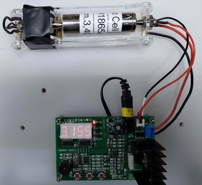
Here we see a cell at the end of its discharge test, showing that it has a capacity of 3,155 mAhrs. This is 93 percent of its 'factory' rating of 3,400 mAhrs. It might be a stretch to describe it as "like new", but if properly used this cell likely has a long and productive life ahead of it.
This tester also displays the cell's capacity in watt hours (Whrs), which is ultimately a more relevant metric since Whrs is a direct measurement of how much energy the pack can deliver. For example, if a pack consists of 42 cells whose individual capacity is 11.6 Whrs, the total pack capacity is approximately 0.5 kWhrs (11.6 Whrs x 42 cells = 487.2 wHrs = 0.4872 kWhrs). To get a "14S/52V" 1 kWhr pack, you would need at least 84 of these cells.
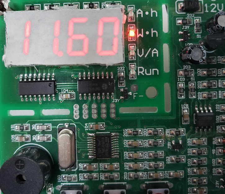
This measurement is much less straightforward than testing capacity, both in doing it and deciding what it means. Cells using any of the lithium-based chemistries tend to cost more than other cells, have a potentially higher energy density, possibly a longer life, and require more care and attention when used. Users of lithium based cells tend to be more 'invested' in these cells than other use-and-discard cells. Because of this, users care about the condition their cells are in, both for economic and safety reasons. Arguably, a cell's internal resistance is an indicator of a cell's state of health (SOH). Also, there is a significant market in previously used cells, and iR is frequently used as a measurement of the cell's SOH.
Whe recycling/repurposing previously used cells, or even using 'new-old-stock' cells, it invariably comes to making a decision of whether it's "worth it" or not to re-use any specific cell. Obviously there are lots of factors involved, such as safety concerns and power/weight ratios.
As a general rule of thumb for our projects, we will responsibly recycle a cell if:
1) it isn't safe to use or store anymore, and/or
2) it's iR has significantly increased over the value at its time of manufacture, or
3) the cell's voltage has dropped to below 1 volt for a period of time.
1) An 'unsafe' cell is one that is puffed (if a pouch), or is leaking electrolyte, or gets excessively warm when charged.
2) An excessive iR value might be 60 milliohms if the cell was at 20 milliohms when manufactured. Some experts will dispose of any cells having an iR of greater than 70. If measuring the iR for an assembled pack, divide the pack's iR by the total number of cells it contains ([S]Series x [P]Parallel).
3) The cell is older than dirt (more than 9 years old) and/or has been stored while deader than a doornail for a period of time, and/or won't take or hold a charge.
The web is full of information about this topic -- have at it.
This Yareo YR1035+ is the device we primarily use to measure a single cell's iR. It injects a 1 kHz AC signal into the cell during the measurement process and 'somehow' derives the internal resistance (iR) of the cell from its impedance. We simply assume that it's accurate enough to obtain a baseline measurement. When compared to the iR measurement obtained from the ZH-YU ZB106+ shown above, it is typically 8-10 mOhms lower. Both devices use a "4 wire" measurement technique, and we have no way to prove which method is more accurate. On top of that, a cell's iR changes under different conditions, including it's state-of-charge (SOC) and temperature, so accuracy is also dependent on using standardized testing conditions, which we don't use. A deeper dive into this subject on the web suggests that the "AC iR" test we use here tends to be more accurate than the "DC iR" approach used by the ZB106 and other iR testers. It is said that because the AC (alternating current) method of calculating iR is based on the cell's impedance and not its resistance, it is only marginally affected by the cell's SOC and its temperature. Another factor favoring the AC testing method is that cell manufacturers tend to use this 1 kHz AC signal injection method when arriving at the cell's iR rating in the published data specifications for that cell.
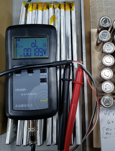
For our purposes, we are less concerned with accuracy (getting the 'right' measurement) than we are with repeatability. We want to know if a cell's internal resistance is relatively stable over time, or whether it is increasing. A stable iR reading suggests that the battery itself is not degrading significantly due to internal damage. It's a bit like taking blood pressure readings in humans -- if the values increase rapidly, it might be a sign of problems to come. We use the YR1035+ device simply because it is more convenient to use, and appears to have a high degree of repeatability in its measurements, and is based on the manufacturers specification for that cell when new.
The following table shows data from two real-world tests of six 18650 cells manufactured by Panasonic (model NCR1865J2). I performed the tests in the "HJ" column, while the cells' seller performed the tests whose results are in the "BCH" column. The cells are described as "unused" as opposed to "new," presumably meaning they were manufactured some time ago and had simply been sitting in some kind of storage environment since. The cells are "unwrapped," meaning they have no external identifying marks or protective shrinkwrap. The table shows both capacity and internal resistance results for each cell, one done by us and one done by the seller of the cells. The data sheet for this cell states that the nominal capacity for these cells when new is 3,400 mAhrs. These cells may have been specifically manufactured for use in Tesla cars.
Note that the results are not only directly dependent on the equipment used to measure the cells, but also the following:
Testing Conditions.
| Cell ID # |
HJ Capacity (mAhrs) |
BCH Capacity (mAhrs) |
Difference (mAhrs) |
HJ Internal R (mOhms) |
BCH Internal R (mOhms) |
Difference (mOhms) |
AVG Watt Hours (Whrs) |
|---|---|---|---|---|---|---|---|
| 1 | 3,152 | 3,275 | 123 | 22 | 11.5 | ||
| 2 | 3,163 | 3,285 | 122 | 23 | 11.6 | ||
| 3 | 3,155 | 3,234 | 79 | 24 | 11.57 | ||
| 4 | 3,130 | 3,439 | 309 | 25 | 11.49 | ||
| 5 | 3,163 | 3,438 | 275 | 23 | 11.61 | ||
| 6 | 3,155 | 3,471 | 316 | 23 | 11.57 |
Return to Top of Page Return to Main Menu
Watch Micah Toll's (ebikeschool.com) great video on tearing down a Hailong SO-39 pack