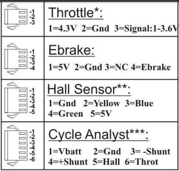
Chart from Grin CA3 manual showing the typical JST-SM (inline) series connectors used until the switch was made to the combined round locking series around 2020. Shown here are the female side of the connectors, which are attached via cables to the controller. The pin numbers are consistent between the male and female plugs, and are an absolute reference.
Showing the use of JST-SM (male and female) inline connectors to connect the CA3-DP and other controls to an early Grinfineon controller.
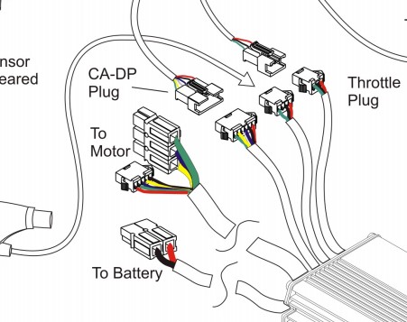
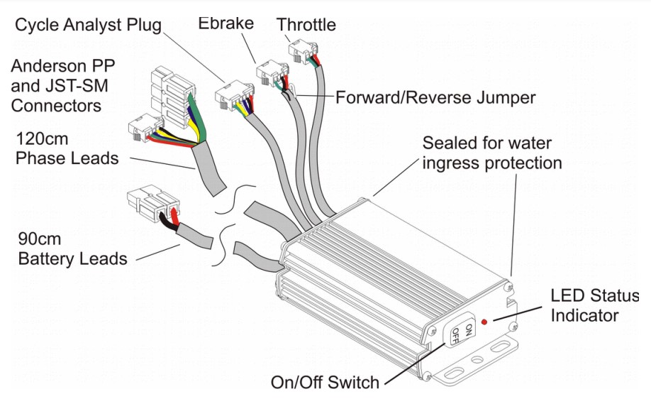
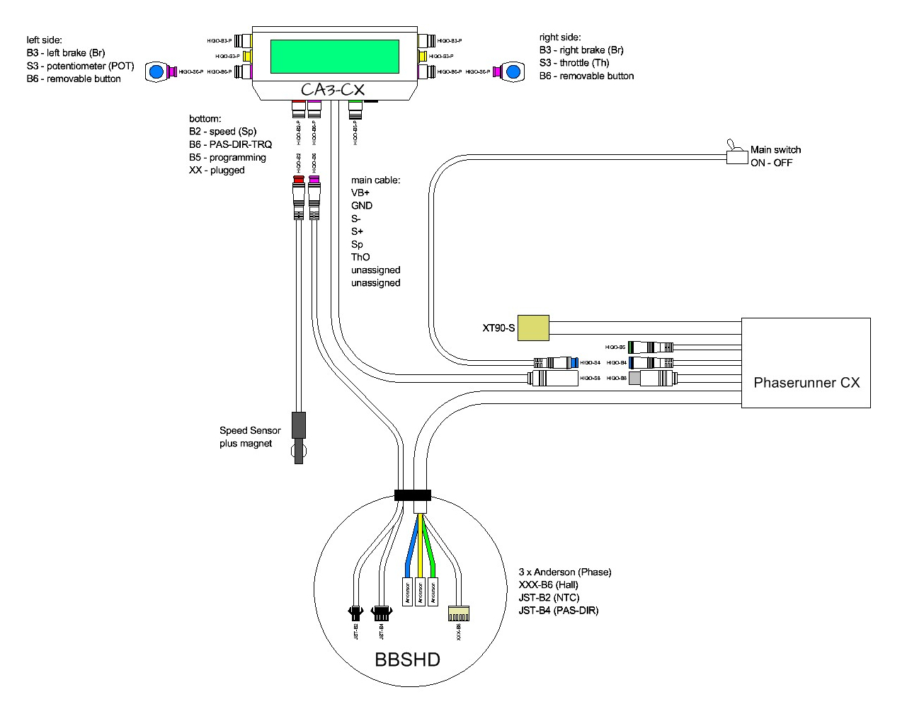
The following diagram focuses on the Grinfineon controller itself. Note that the plugs are typically female because they represent the "hot" side of the circuit. The notable exception is the traction battery connector where the "hot" side is the battery, not the controller. Also note the optional wires for the Fwd/Rev jumper, and (un-labeled) temperature sensor. These wires are typically unterminated and hidden under the shrinkwrap near the connector.
Return to Top of Page Return to Main Menu
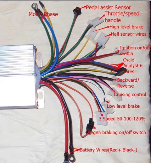
This shows a typical 'cheap' Chinese Infineon class controller with the connector style used on many early model ebikes. Notice the relatively skimpy phase wires, terminated with simple ring terminals.
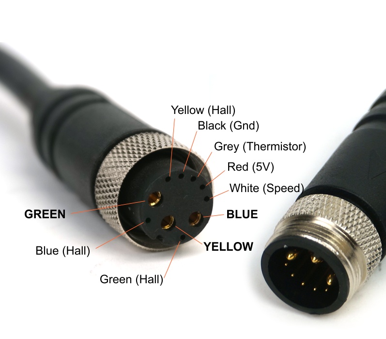
Beginning in about 2020, Grin switched to using "L10" style connectors between their controllers and motors. The female plug is on the controller ("hot") side. These 10 wire connectors carry the three phases over thicker power wires and have an additional 7 wires for Hall power+signals, temperature data, and speed data. While more expensive and harder to use in the DIY environment than earlier connectors, they are very reliable in use and probably worth the tradeoff. We buy extra cables from Grin and add JST-SM and Anderson plugs to make adapters as needed.
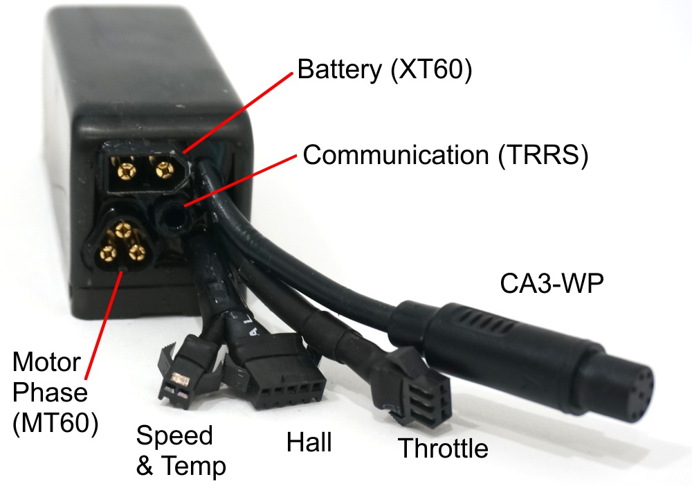
Some newer versions of Grin's Phaserunner controller use phase wires which can also be unplugged at the controller side. In general this is probably a good idea, but in practice it turns out that the two conductor (keyed, but not locking) XT60 plug coming from the traction battery will slip out without too much provocation. A dab of hot glue on the plug or a way of fastening the cable very close to the XT60 socket will be necessary to avoid a total power loss in mid-ride.
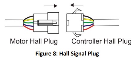
Showing the five wires needed (5VDC power & ground, plus three Hall sensor signals) to connect the controller and motor, when running in "sensored" mode.
The following shows the above Hall sensor plug, as well as the three heavier phase wires. All traction power used by the motor must go three these phase wires.
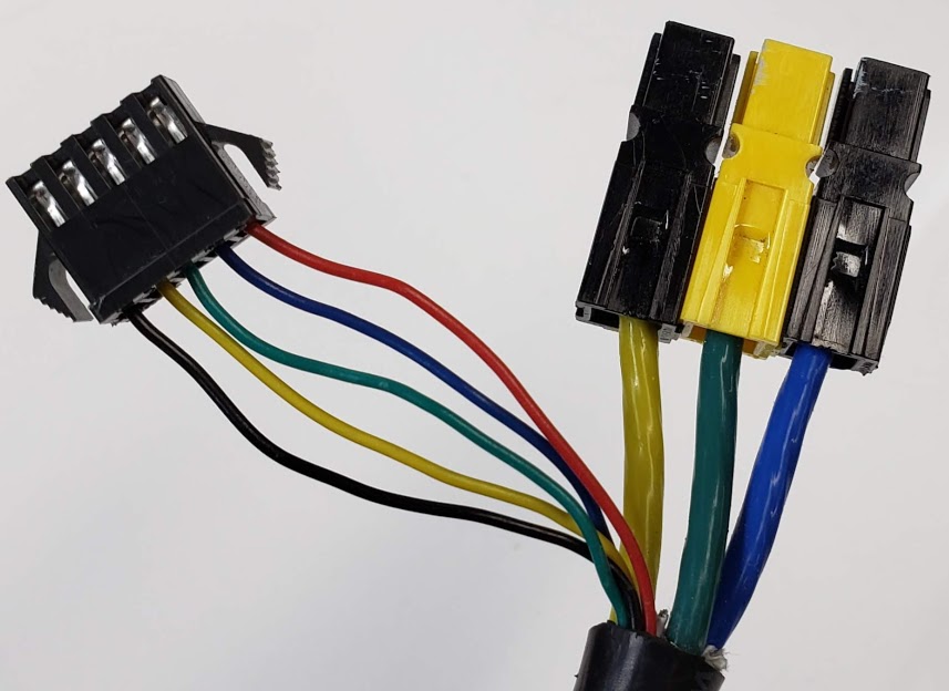
For the correct operation of the motor, the three phase wires must be connected in the right order. Some smart controllers can figure this out for themselves. The connectors shown here are the "small" Anderson PowerPoles.
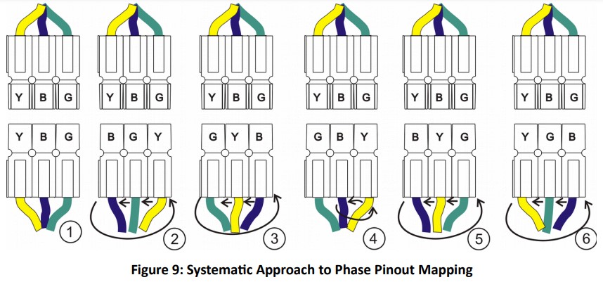
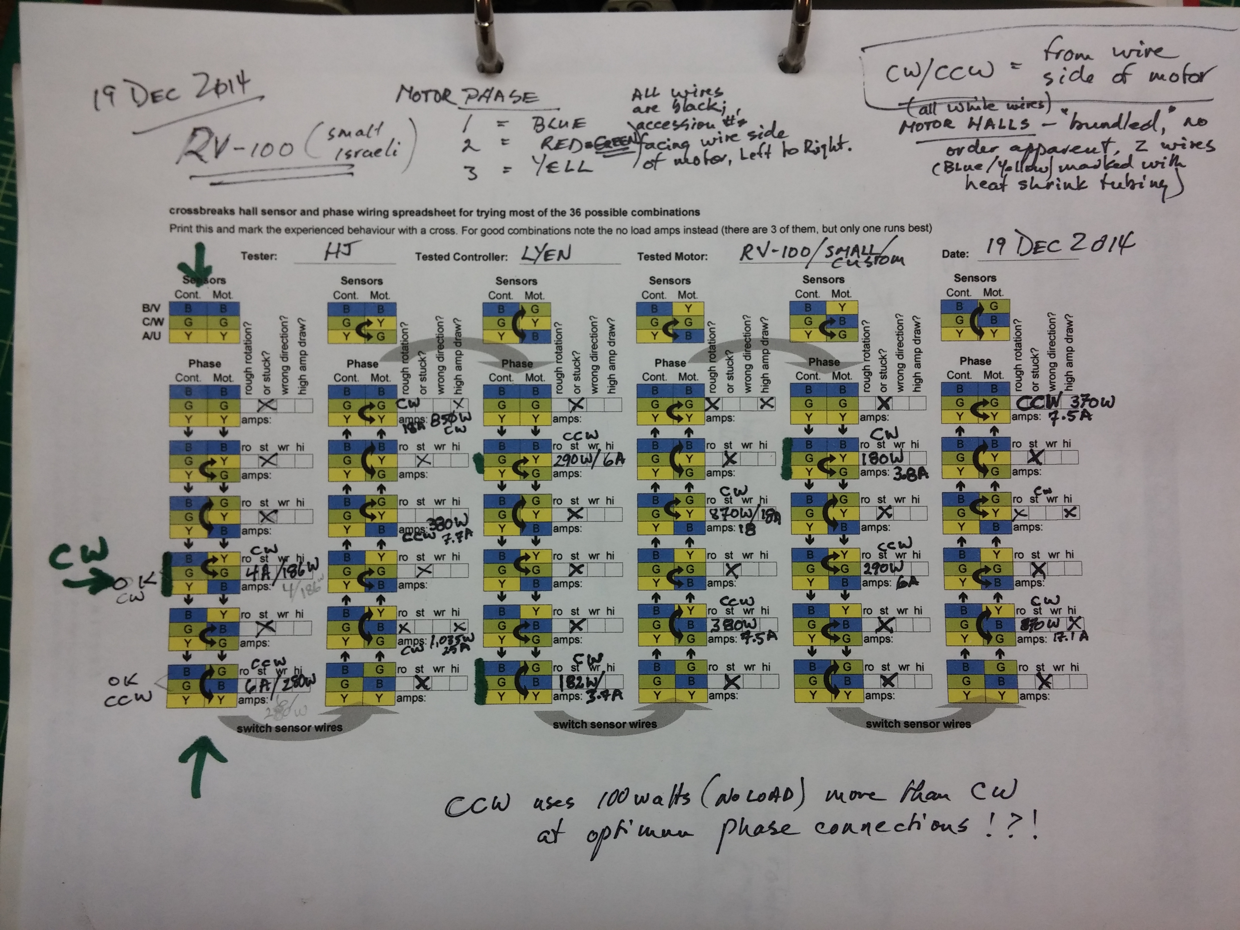
To make it easier to perform the trial-and-error process sometimes required to get a specific controller and motor to work together, using a worksheet listing all possible wire combinations can be extremely useful.
Return to Top of Page Return to Main Menu
Some ebike controllers have provisions for allowing their internal firmware to be re-programmed by the user. This includes all Grin controllers and some in the Infineon class.
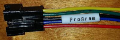
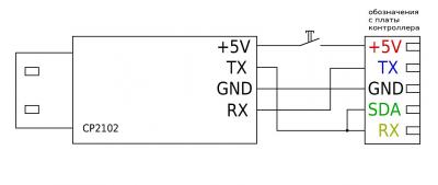
This shows the wire mapping to the USB connector that plugs into the computer running the programming app.
Return to Top of Page Return to Main Menu
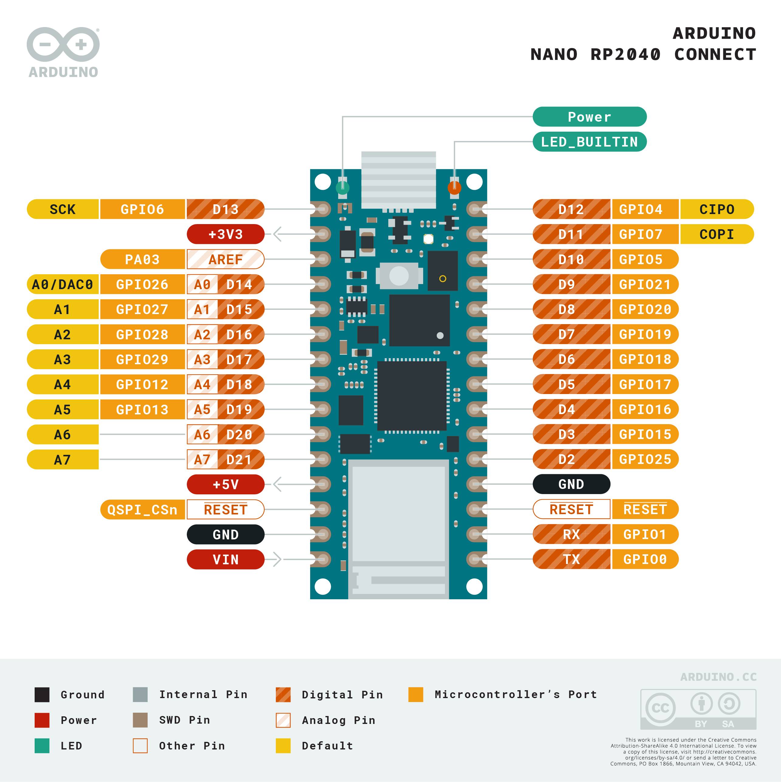
Pinout diagram of the new (2021) Arduino/Raspberry Pi RP2040 "Connect" microcontroller board that we're planning on using for Stella's security system.
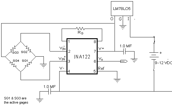
Somewhat generic circuit diagram for a Wheatstone Bridge configured set of four strain gages with an instrumentation amplifier plus on-board linear voltage regulator.
So many connectors, so little time ...
Photo of ...
Photo of ...
Photo of ...
Photo of ...
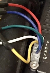
Photo of ...
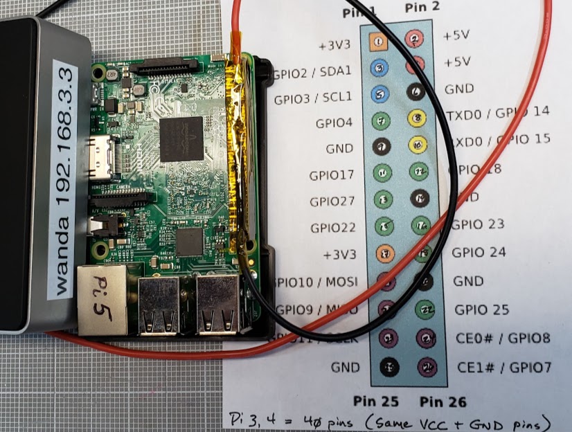
Photo of ...
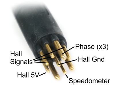
Photo of ...
Photo of ...
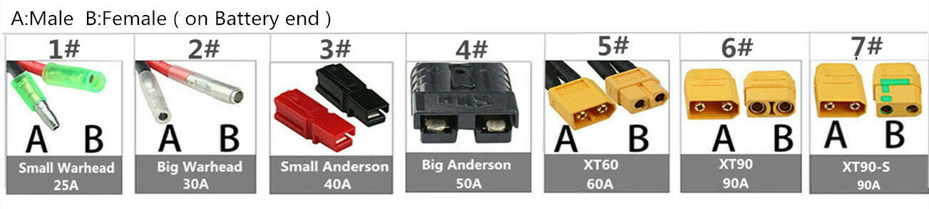
Photo of ...

Photo of ...
Photo of ...
Photo of ...
Photo of ...
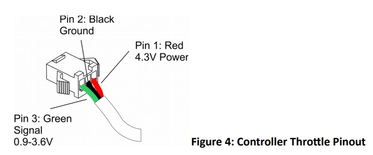
The CA-DP pinout diagram.
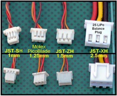
Photo of small JST and Molex connectors.
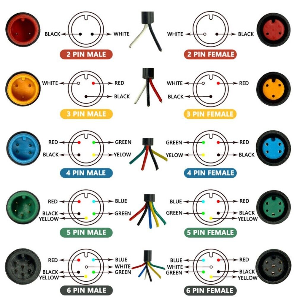
Higo/Julet 2 to 6 pin "standard" connectors, by housing and wire colors. Higo/Julet connectors are rated at 2A for each pin/conductor, and are described as "waterproof" in most of the literature.
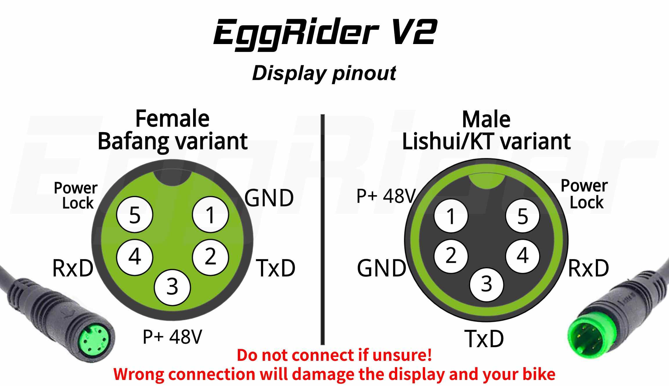
Higo/Julet 5 pin "green" connector used to connect displays to controllers. Shown here are two variants: Bafang and Lishui/KT (KunTeng) controllers.
Photo courtesy of user stancecoke at ES [https://endless-sphere.com/sphere/threads/the-dreaded-error-30-communication-error-resolved.120797/#post-1770501], who credits the Eggrider site for the photo.